Chapter 4 Parameters
4-45
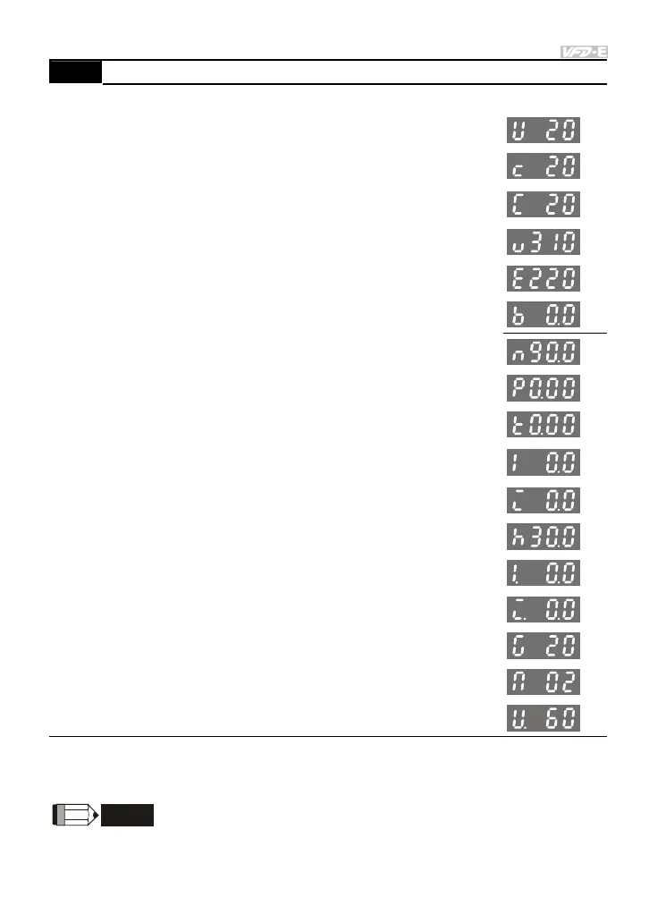
00.04 Content of Multi-function Display
Factory Setting: 0
Settings 0 Display the content of user-defined unit (Uxxx)
1
Display the counter value which counts the number of
pulses on TRG terminal (c)
2
Display PLC D1043 value (C)
(NOT for VFD*E*C models)
3
Display the actual DC BUS voltage in VDC of the AC
motor drive (u)
4
Display the output voltage in VAC of terminals U/T1,
V/T2, W/T3 to the motor (E)
5 Display PID analog feedback signal value in % (b)
6
Display the power factor angle in º of terminals U/T1,
V/T2, W/T3 to the motor (n)
7
Display the output power in kW of terminals U, V and W
to the motor (P)
8
Display the estimated value of torque in Nm as it relates
to current (t)
9
Display the signal of AVI analog input terminal in V (I)
10
Display the signal of ACI analog input terminal in mA or
display the signal of AVI2 analog input terminal in V (i)
11
Display the temperature of IGBT (h) in °C
12 Display AVI3/ACI2 level (I.)
13 Display AVI4/ACI3 level (i.)
14 Display PG speed in RPM (G)
15 Display motor number 00~03 (M)
16 Display F*Pr.00.05
When Pr00.03 is set to 03, the display is according to the setting of Pr00.04.
When Pr.00.04 is set to 0 or 16, please refer to Pr.00.05 for details.
Related parameter: Pr.00.05 (User Defined Coefficient K)
NOTE
Please refer to Appendix B.8 KPE-LE02 for the 7-segment LED Display of the Digital Keypad.