Chapter 4 Parameters
4-82
1 1
Weights
Bit
Relay 1
MO1
0 00 00 0
MO2/RA2
MO3/RA3
MO4/RA4
MO5/RA5
MO6/RA6
MO7/RA7
0=not used
1=Used by PLC
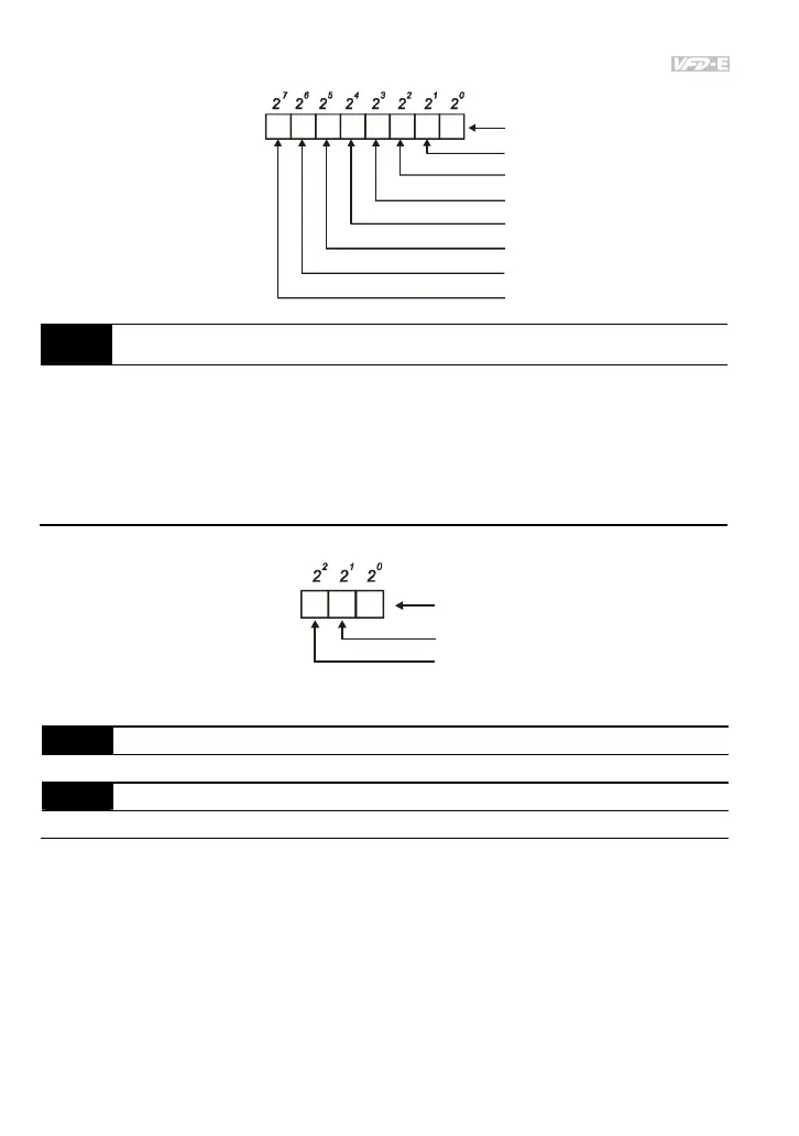
03.10 The Analog Output Used by PLC (NOT for VFD*E*C models)
Settings Read Only Factory display: 0
Bit0=1: AFM used by PLC
Bit1=1: AO1 used by PLC
Bit2=1: AO2 used by PLC
The equivalent 1-bit is used to display the status (used or not used) of each analog output. The
value that Pr.03.10 displays is the result after converting 1-bit binary into decimal value.
0
Weights
Bit
0=not used
1=Used by PLC
AFM
12
AO1 (optional)
AO2 (optional)
For Example:
If Pr.03.10 displays 1, it means that AFM is used by PLC.
03.11 Brake Release Frequency Unit: Hz
Settings 0.00 to 20.0Hz Factory Setting: 0.00
03.12 Brake Engage Frequency Unit: Hz
Settings 0.00 to 20.0Hz Factory Setting: 0.00
These two parameters are used to set control of mechanical brake via the output terminals
(Relay or MO1) by setting Pr.03.00~03.01.
When Pr.03.00~03.01 is set to 21, the multi-function output terminal will be activated when the
output frequency reaches Pr.03.11. When the AC motor drive stops and the output frequency
reaches Pr.03.12, this multi-function output terminal will be activated.
Related parameters: Pr.03.00(Multi-function Output Relay (RA1, RB1, RC1)) and
Pr.03.01(Multi-function Output Terminal MO1)