Chapter 4 Parameters
4-99
12345 0
0=N.O
1=N.C
MI1
MI2
MI3
MI4
MI5
MI6
Weights
Bit
7891011 6
MI7
MI8
MI9
MI10
MI11
MI12
This parameter is used to set the response time of digital input terminals MI1~MI6.
This parameter is to delay the signals on digital input terminals. 1 unit is 2 msec, 2 units are 4
msec, etc. The delay time is to debounce noisy signals that could cause the digital terminals to
malfunction.
The AC motor drive will check the status of multi-function input terminals every 2ms. It will only
confirm the command and change the status when the input terminals status is changed. Thus,
the delay time from command input to execution is 2msec+ (Pr.04.10+1) X 2ms. Suppose that
Pr.04.10 is set to 4, the delay time will be 12ms.
04.24
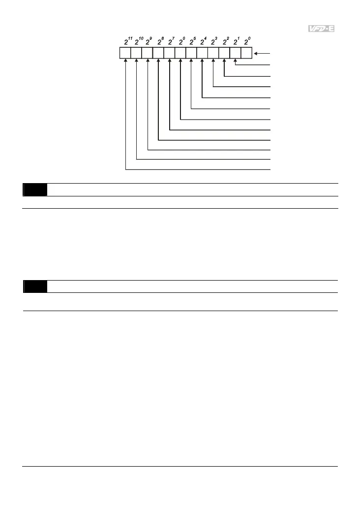
The Digital Input Used by PLC (NOT for VFD*E*C models)
Settings Read Only Factory display: 0
Display Bit0=1: MI1 used by PLC
Bit1=1: MI2 used by PLC
Bit2=1: MI3 used by PLC
Bit3=1: MI4 used by PLC
Bit4=1: MI5 used by PLC
Bit5=1: MI6 used by PLC
Bit6=1: MI7 used by PLC
Bit7=1: MI8 used by PLC
Bit8=1: MI9 used by PLC
Bit9=1: MI10 used by PLC
Bit10=1: MI11 used by PLC
Bit11=1: MI12 used by PLC
04.10
Digital Terminal Input Debouncing Time
Unit: 2ms
Settings
1 to 20
Factory Setting: 1