Chapter 4 Parameters
4-81
03.09
The Digital Output Used by PLC (NOT for VFD*E*C models)
Settings Read Only Factory display: 0
Bit0=1: RLY used by PLC
Bit1=1: MO1 used by PLC
Bit2=1: MO2/RA2 used by PLC
Bit3=1: MO3/RA3 used by PLC
Bit4=1: MO4/RA4 used by PLC
Bit5=1: MO5/RA5 used by PLC
Bit6=1: MO6/RA6 used by PLC
Bit7=1: MO7/RA7 used by PLC
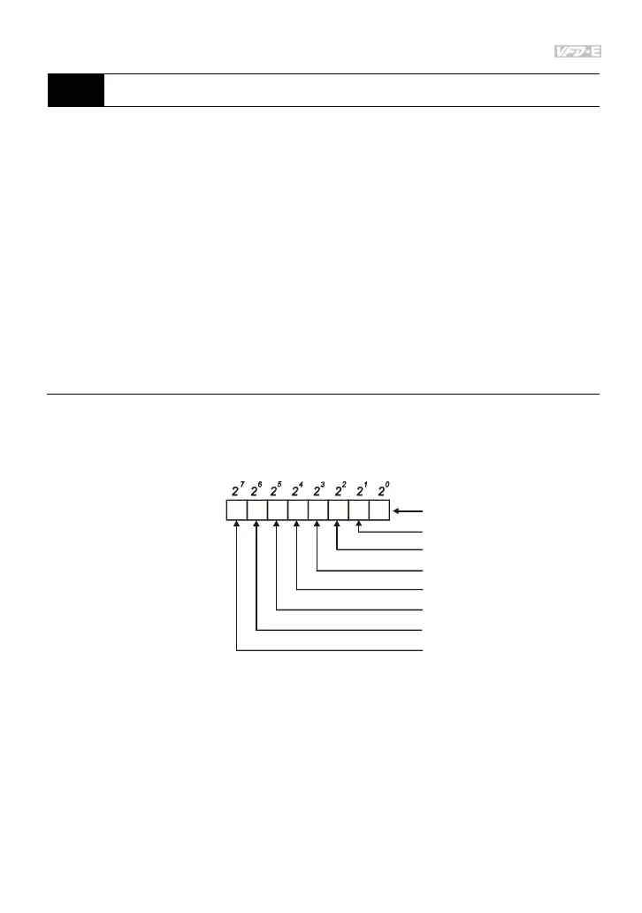
The equivalent 8-bit is used to display the status (used or not used) of each digital output. The
value that Pr.03.09 displays is the result after converting 8-bit binary into decimal value.
For standard AC motor drive, it only has 2-bit (bit0 and bit1). When extension card is installed,
the number of the digital output terminals will increase according to the extension card. The
maximum number of the digital output terminals is shown as follows.
1 0
Weights
Bit
Relay 1
MO1
3 25 47 6
MO2/RA2
MO3/RA3
MO4/RA4
MO5/RA5
MO6/RA6
MO7/RA7
0=not used
1=Used by PLC
For example: when Pr.03.09 is set to 3 (decimal) = 00000011 (binary) that indicates Relay1
and MO1 are used by PLC. (Pr.03.09= 2
0
+2
1
=3)