Chapter 3 Keypad and Start Up
3-3
3.3 Trial Run
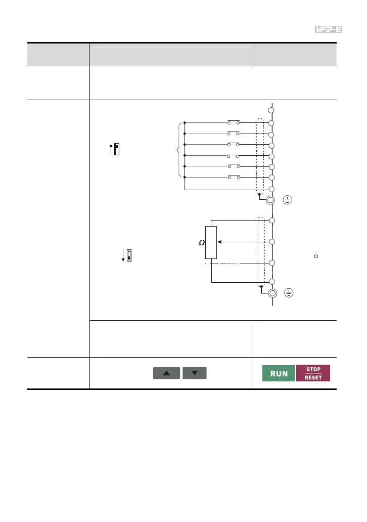
The factory setting of the operation source is from the external terminal (Pr.02.01=2).
1. Both MI1-DCM and MI2-DCM need to connect a switch for switching FWD/STOP and
REV/STOP.
2. Please connect a potentiometer among AVI, 10V and DCM or apply power 0-10Vdc to
AVI-DCM (as shown in figure 3-1)
Operation
Method
Frequency Source
Operation Command
Source
Operate from the
communication
When setting communication by the PC, it needs to use VFD-USB01 or
IFD8500 converter to connect to the PC.
Refer to the communication address 2000H and 2101H setting for details.
Operate from
external signal
* Don't apply the mains voltage directly
to above terminals.
E
MI1
MI2
MI3
MI4
MI6
MI5
DCM
+24V
FWD/Stop
REV/Stop
Multi-step 1
Multi-step 2
Multi-step 3
Multi-step 4
Digital Signal Common
Factory
setting
Sw1
NPN
PNP
Factory setting:
NPN Mode
VI
CI
CM
+10V
5K
3
2
1
Power supply
+10V 3mA
Master Frequenc
0 to 10V 47K
Analog Signal Common
E
Sw2
AVI2
ACI
Factory setting:
ACI Mode
ACI/AVI2 switch
4-20mA/0-10V
Figure 3-1
MI3-DCM (Set Pr.04.05=10)
MI4-DCM (Set Pr.04.06=11)
External terminals input:
MI1-DCM
MI2-DCM
Operate from the
optional keypad
(KPE-LE02)