D-23
The common control circuit
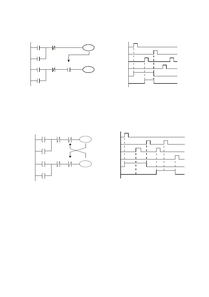
Example 4: condition control
X3
Y1
X1
Y1
X4
Y2
X2
Y2
Y1
X1
X3
X2
X4
Y1
Y2
X1 and X3 can start/stop Y1 separately, X2 and X4 can start/stop Y2 separately and they are all
self latched circuit. Y1 is an element for Y2 to do AND function due to the normally open contact
connects to Y2 in series. Therefore, Y1 is the input of Y2 and Y2 is also the input of Y1.
Example 5: Interlock control
X1
X3
Y1
Y1
X2
X4
Y2
Y2
Y1
Y2
X1
X3
X2
X4
Y1
Y2
The figure above is the circuit of interlock control. Y1 and Y2 will act according to the start
contact X1 and X2. Y1 and Y2 will act not at the same time, once one of them acts and the
other won’t act. (This is called interlock.) Even if X1 and X2 are valid at the same time, Y1 and
Y2 won’t act at the same time due to up-to-down scan of ladder diagram. For this ladder
diagram, Y1 has higher priority than Y2.