Chapter 4 Parameters
4-157
10.06 Primary Delay Filter Time Unit: second
Settings 0.0 to 2.5 sec Factory Setting: 0.0
It is used to set the time that required for the low-pass filter of PID output. Increasing the
setting, it may affect the drive’s response speed.
The frequency output of PID controller will filter after primary delay filter time. It can smooth the
change of the frequency output. The longer primary delay filter time is set, the slower response
time it will be.
The unsuitable primary delay filter time may cause system oscillation.
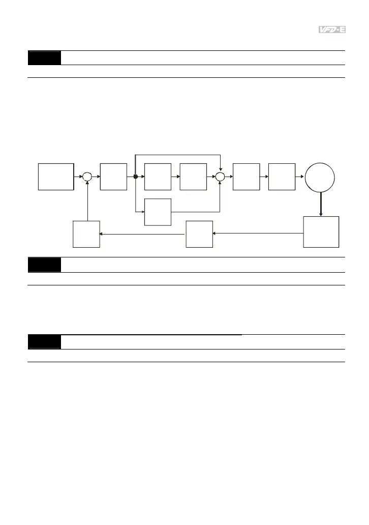
PID control can be used for speed, pressure and flow control. It needs to use with the relevant
equipment of sensor feedback for PID control. Refer to the following for the closed-loop control
diagram.
P
10.02
I
10.03
D
10.04
10.05
10.10
10.07
10.06
10.01
+
-
+
+
+
Setpoint
Input Freq.
Gain
PID
feed ba ck
Integral
gain
limit
Output
Freq.
Limit
Digital
filter
Freq
Command
Motor
Sensor
10.07
PID Output Frequency Limit
Unit: %
Settings 0 to 110 % Factory Setting: 100
This parameter defines the percentage of output frequency limit during the PID control. The
formula is Output Frequency Limit = Maximum Output Frequency (Pr.01.00) X Pr.10.07 %.
This parameter will limit the Maximum Output Frequency. An overall limit for the output
frequency can be set in Pr.01.07.
Related parameter: Pr.01.00(Maximum Output Frequency (Fmax))
10.08
PID Feedback Signal Detection Time
Unit: second
Settings 0.0 to d 3600 sec Factory Setting: 60.0
This parameter defines the time during which the PID feedback must be abnormal before a
warning (see Pr.10.09) is given. It also can be modified according to the system feedback
signal time.
If this parameter is set to 0.0, the system would not detect any abnormality signal.
If it doesn’t receive PID feedback signal over Pr.10.08 setting, the feedback signal fault will
occur and please refer to Pr.10.09 for the fault treatment.
Related parameter: Pr.10.09(Treatment of the Erroneous PID Feedback Signals)