D-16
The structure and explanation of ladder diagram:
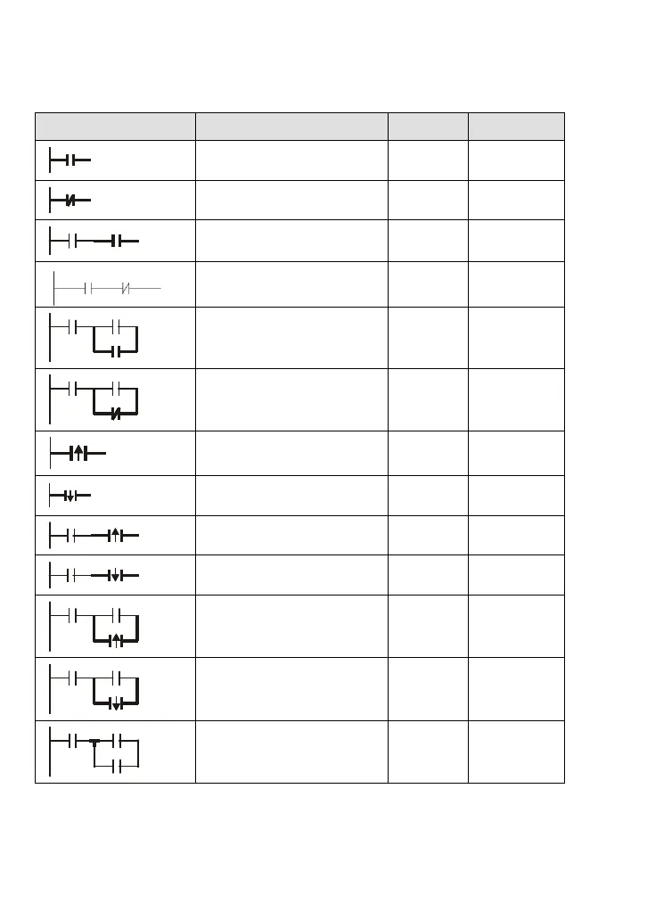
Ladder Diagram Structure Explanation Command Equipment
Normally open, contact a LD X, Y, M, T, C
Normally closed, contact b LDI X, Y, M, T, C
Serial normally open AND X, Y, M, T, C
Serial normally close ANI
X, Y, M, T, C
Parallel normally open OR X, Y, M, T, C
Parallel normally closed ORI X, Y, M, T, C
Rising-edge trigger switch LDP X, Y, M, T, C
Falling-edge trigger switch LDF X, Y, M, T, C
Rising-edge trigger in serial ANDP X, Y, M, T, C
Falling-edge trigger in serial ANDF X, Y, M, T, C
Rising-edge trigger in parallel ORP X, Y, M, T, C
Falling-edge trigger in parallel ORF X, Y, M, T, C
Block in serial ANB none