Chapter 4 Parameters
4-101
04.25 The Analog Input Used by PLC (NOT for VFD*E*C models)
Settings Read Only Factory display: 0
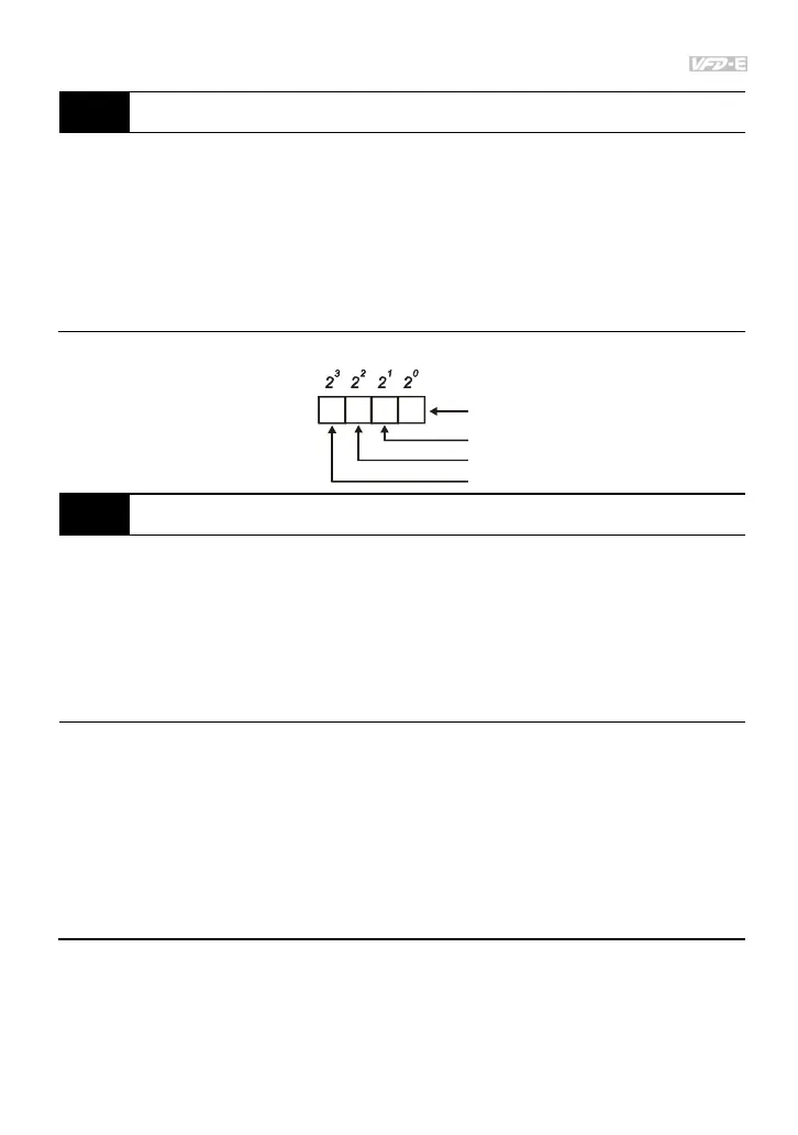
Display Bit0=1: AVI used by PLC
Bit1=1: ACI/AVI2 used by PLC
Bit2=1: AI1 used by PLC
Bit3=1: AI2 used by PLC
The equivalent 2-bit is used to display the status(used or not used) of each analog input. The
value for Pr.04.25 to display is the result after converting 2-bit binary into decimal value.
1
0
Weights
Bit
0=not used
1=used by PLC
AVI
ACI/AVI2
13
2
AI1 (optional)
AI2 (optional)
04.26 Display the Status of Multi-function Input Terminal
Settings Read Only Factory display: ##
Display Bit0: MI1 Status
Bit1: MI2 Status
Bit2: MI3 Status
Bit3: MI4 Status
Bit4: MI5 Status
Bit5: MI6 Status
Bit6: MI7 Status
Bit7: MI8 Status
Bit8: MI9 Status
Bit9: MI10 Status
Bit10: MI11 Status
Bit11: MI12 Status
The multi-function input terminals are falling-edge triggered. For standard AC motor drive
(without extension card), there are MI1 to MI6 and Pr.04.26 will display 63 (111111) for no
action.