Chapter 4 Parameters
4-172
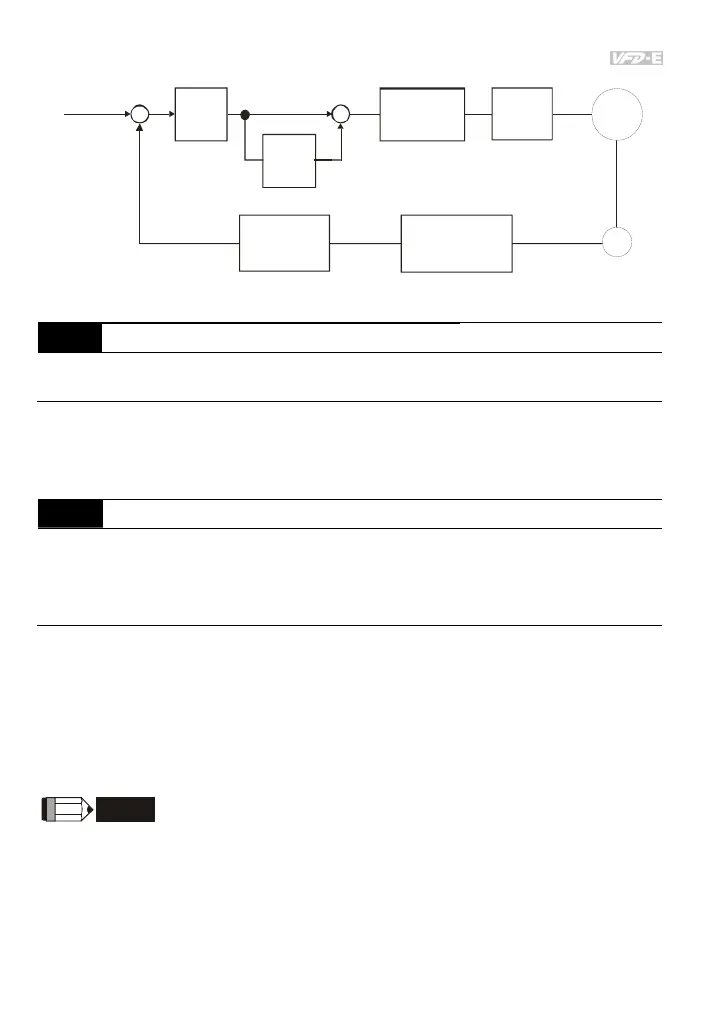
Freq ue ncy
command
Spe ed
detection
P
13.03
+
-
+
+
I
13.04
Motor
PG
Speed con tro l
output frequency
limit
13.05
Speed feedback
filter
13.09
Output
freq ue ncy
upper limit
01.07
outpu
fr eq ue ncy
(H)
PG feedback speed control
PG typ e, pul se r an ge
and moto r pol e number
13.00, 13.01, 13.02
13.07 Time for Feedback Signal Fault Unit: second
Settings 0.1 to 10.0 sec Factory Setting: 1.0
0.0 Disabled
This parameter defines the time during which the PID feedback must be abnormal before a
warning (see Pr.13.08) is given. It also can be modified according to the system feedback
signal time.
If this parameter is set to 0.0, the system would not detect any abnormality signal.
Related parameter: Pr.13.08(Treatment of the Feedback Signal Fault)
13.08 Treatment of the Feedback Signal Fault
Factory Setting: 1
Settings 0 Warn and RAMP to stop
1 Warn and COAST to stop
2 Warn and keep operating
AC motor drive action when the feedback signals (analog PID feedback or PG (encoder)
feedback) are abnormal.
Setting Pr.13.08 to 0: When the feedback signal fault occurs, it will display “PGEr” on the
digital keypad and the stop to 0Hz by Pr.01.10/Pr.01.12 setting.
Setting Pr.13.08 to 1: When the feedback signal fault occurs, it will display “PGEr” on the
digital keypad and the motor will free run to stop.
Setting Pr.13.08 to 2: When the feedback signal fault occurs, it will display “PGEr” on the
digital keypad and the motor will keep running.
It needs to press “RESET” to clear the warning message “PGEr” displayed on the keypad.
NOTE
The digital keypad is optional. Please refer to Appendix B for details. When using without this optional
keypad, the FAULT LED will be ON once there are fault messages or warning messages from the
external terminals.