D-38
D.4.10 Communication Addresses for Devices (only for PLC2 mode)
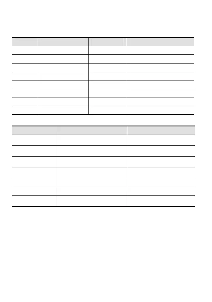
Device Range Type Address (Hex)
X 00–17 (octal) Bit 0400-040F
Y 00–17 (octal) Bit 0500-050F
T 00-15 Bit/word 0600-060F
M 000-159 Bit 0800-089F
M 1000-1031 Bit 0BE8-0C07
C 0-7 Bit/word 0E00-0E07
D 00-29 Word 1000-101D
D 1000-1044 Word 13E8-1414
D.4.11 Function Code (only for PLC2 mode)
Function Code Description Supported Devices
H1 Read coil status Y, M, T, C
H2 Read input status X, Y, M, T, C
H3 Read one data T, C, D
H5 Force changing one coil status Y, M, T, C
H6 Write in one data T, C, D
HF Force changing multiple coil status Y, M, T, C
H10 Write in multiple data T, C, D
NOTE:
In PLC1 mode, the Modbus communication will correspond to the registers of motor drive.
In PLC2 mode, the Modbus communication will correspond to the registers of internal PLC.
For example:
In PLC1 mode, communication register 0400H corresponds to parameter 04.00.
In PLC2 mode, communication register 0400H corresponds to X0.