D-26
When input X0 is ON, output coil Y1 will be ON at the same time due to the corresponding
normally close contact OFF makes timer T10 to be OFF. Output coil Y1 will be OFF after
delaying 100 seconds (K1000*0.1 seconds =100 seconds) once input X0 is OFF and T10 is
ON. Please refer to timing chart above.
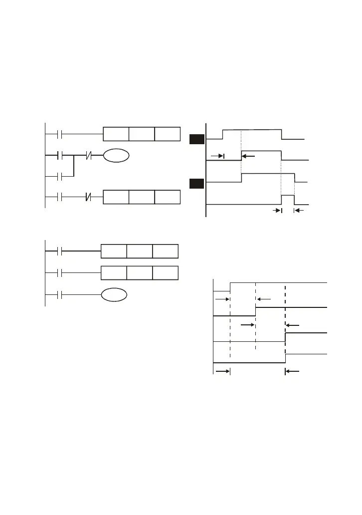
Example 11: Output delay circuit
In the following example, the circuit is made up of two timers. No matter input X0 is ON or OFF,
output Y4 will be delay.
T5
T5
TMR
Y4
T6
X0
K50
Y4
T6
Y4
TMR
X0
K30
X0
T5
Y0
T6
5 seconds
3 seconds
Example12: Extend Timer Circuit
T12TMR Kn2
T11
X0
TMR
Y1
T11
Kn1
T12
In this circuit, the total delay time from input
X0 is close and output Y1 is ON= (n1+n2)* T.
where T is clock period.
X0
Y1
T11
T12
n1*
n2*
T
T
(n1+n2)*
T