D-54
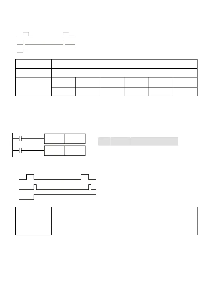
Timing Diagram:
X0
M0
Y0
a scan time
LD M0 Load the contact A of M0
SET Y0 Y0 latched (ON)
Mnemonic Function
PLF Falling-edge output
Operand
X0~X17 Y0~Y17 M0~M159 T0~15 C0~C7 D0~D29
--
-- -- --
Explanations:
When X0= ON→OFF (falling-edge trigger), PLF command will be executed and M0 will send the
pulse of one time which the length is the time for scan one time.
Program Example:
Ladder diagram: Command code: Operation:
X0
M0
PLF
M0
Y0SET
Timing Diagram:
a scan time
X0
M0
Y0
LD X0 Load A contact of X0
PLF M0 M0 falling-edge output
LD M0 Load the contact A of M0
SET Y0 Y0 latched (ON)
Mnemonic Function
END Program End
Operand
None
Explanations:
It needs to add the END command at the end of ladder diagram program or command program. PLC
will scan from address o to END command, after executing it will return to address 0 to scan again.