Chapter 3: D-Show Profile Control Overview 27
Solo Safe Mode If the Safe LED is flashing, the channel will
not respond to solo commands (it will not be muted if an-
other channel’s solo button is pressed). If the LED is off, that
channel will be silenced when soloing another channel.
Pressing a channel Safe switch for the Selected Channel tog-
gles the current state of that channel.
Bus Assignment Indicators
These green LEDs indicate Group bus assignments, and can
also show VCA or Mute Group membership for each channel.
By default, Group bus assignment is displayed.
Group Bus Assignment
◆ If the LR LED is lit, the input channel feeds the Left and
Right Main busses in either L–R or L–C–R panning mode (re-
gardless of the Stereo Pan LED status).
◆ If the C/M LED is lit, the input channel feeds the C (center)
bus from the pan in L–C–R mode, or the M (mono) bus before
the pan. Stereo channels are summed to the mono bus.
◆ If a bus LED (1–8) is lit, the channel is feeding the corre-
sponding Group(s). If an LED is off, the channel is not feeding
that Group. The Bus Indicators can also show VCA and Mute
Group membership.
VCA Membership
◆ When VCA Show Members mode is enabled, Group indica-
tors flash to indicate VCA membership.
Mute Groups
◆ When the Mute Groups Show Members switch is pressed,
the Group indicators flash to indicate Mute Group assign-
ments. A flashing LED indicates that the channel is assigned
to the corresponding Mute Group (1–8).
Stereo Pan LED
This LED indicates when the channel is assigned to a stereo
Groups bus.
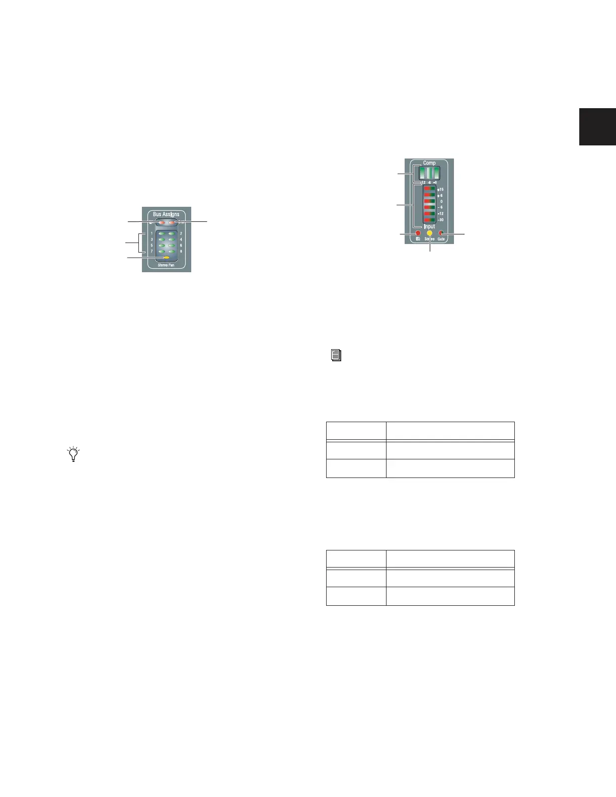
Input Channel Metering
Each Input Channel provides a gain reduction meter, input
level meter, and LEDs to indicate EQ, Gate, and stereo status.
Comp Gain Reduction Meter
A 3-segment meter displays gain reduction for the channel
compressor/limiter. Green LEDs are used for all segments.
Input Level Meter
A 6-segment meter displays input level and indicates clipping.
Bi-color LEDs are used for all segments, as shown in the fol-
lowing table. Clipping is indicated when all LEDs light red.
EQ Status LED
A single red LED indicates EQ In/Out status as shown in the
following table.
Stereo Channel LED
A single yellow LED indicates a stereo input channel. The ste-
reo channel LED flashes if a 10 dB or greater offset is detected
between left and right inputs.
Gate Status LED
A single bi-color LED shows the current Expander or Gate sta-
tus. For LED scales, see “Gate Status LED” on page 107.
Bus Assign indicator LEDs on an Input Channel
Use the Bus Assign switches to route and assign the cur-
rently selected channels to busses (see “Assignable Channel
Section” on page 30).
LR
C/M
1–8
Stereo Pan
Input channel meters and LEDs
For meter scales, see “Channel Meters” on page 107.
Color EQ Status
(none) Not in circuit
Red In circuit
Color Channel Status
(none) Mono
Yellow Stereo
Comp/Lim
Input Level
EQ In/Out
Stereo
Gate LED
Gain Reduction