(28) Install reverse clutch pack (two frictions/one
steel) (Fig. 247).
(29) Install reverse clutch reaction plate with the
flat side down towards reverse clutch (Fig. 248).
(30) Tap reaction plate down to allow installation
of the reverse clutch snap ring. Install reverse clutch
snap ring (Fig. 249).
(31) Pry up reverse reaction plate to seat against
snap ring (Fig. 250).
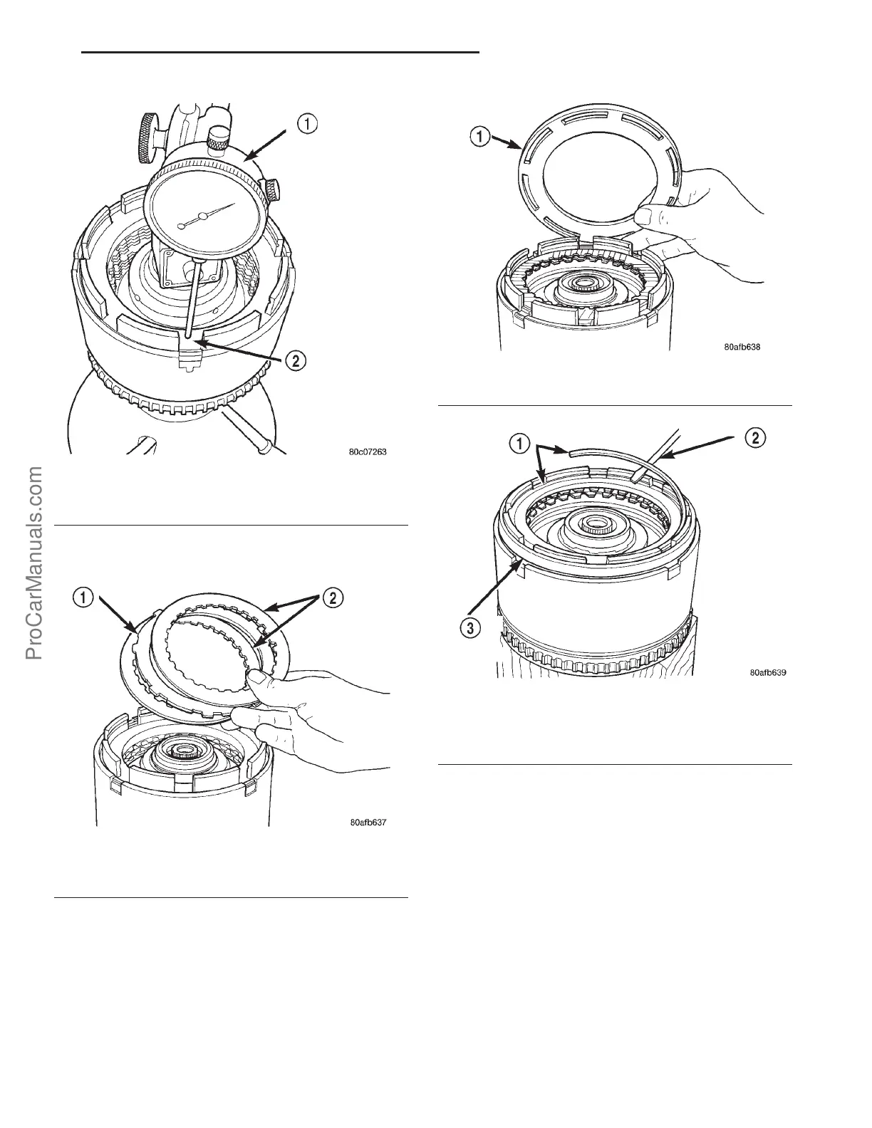
(32) Set up a dial indicator on the reverse clutch
pack as shown in (Fig. 251).
(33) Using moderate pressure, press down and
hold (near indicator) reverse clutch disc with screw-
driver or suitable tool and zero dial indicator (Fig.
252). When releasing pressure, indicator should
advance 0.005-0.010. as clutch pack relaxes.
(34) Apply 30 psi (206 kPa) air pressure to the
reverse clutch hose on Tool 8391. Measure and record
reverse clutch pack measurement in four (4) places,
90° apart.
Fig. 246 Measure OD Clutch Pack Clearance
1 - DIAL INDICATOR
2 - OD/REVERSE REACTION PLATE
Fig. 247 Install Reverse Clutch Pack
1 - REVERSE CLUTCH PLATE
2 - REVERSE CLUTCH DISCS
Fig. 248 Install Reaction Plate
1 - REVERSE CLUTCH REACTION PLATE (FLAT SIDE DOWN)
Fig. 249 Install Reverse Clutch Snap Ring
1 - REVERSE CLUTCH SNAP RING (SELECT)
2 - SCREWDRIVER
3 - REVERSE CLUTCH REACTION PLATE
PL 41TE AUTOMATIC TRANSAXLE 21s - 167
INPUT CLUTCH ASSEMBLY (Continued)
ProCarManuals.com