STP-iXA4507 series Turbomolecular Pump
INSTALLATION OF THE STP PUMP
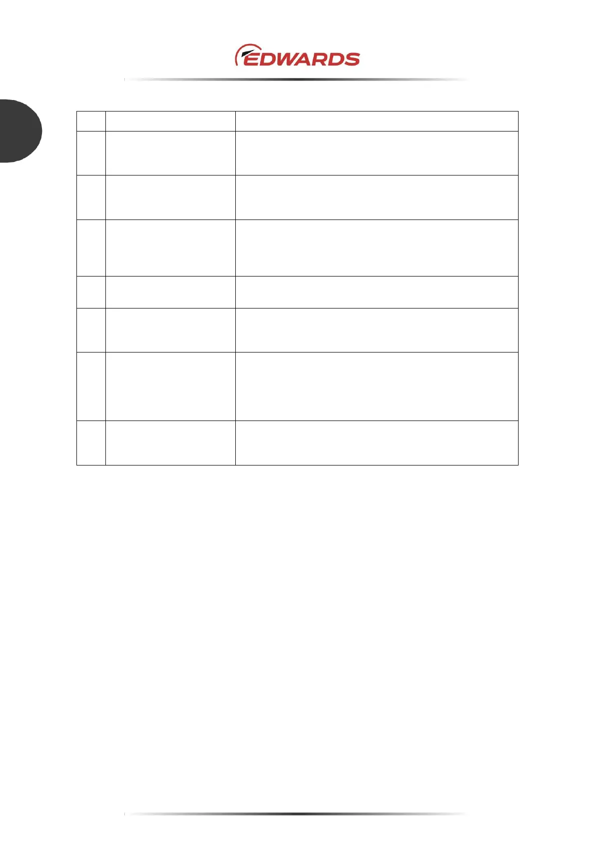
Input power switch.
NEVER stop the power supply to the STP pump while the STP
pump is in rotation.
AC input inlet
For the AC power cable
The input voltage range is between 200 to 240Va.c (50/60Hz)
For RS232 and RS485 (common use) serial communication.
(D-Sub 9 pin)
For the user application.
See Section 5, "SERIAL COMMUNICATION PROTOCOL".
For an optional unit (optional accessory). (X3: 2 pin)
TMS valve can be connected.
I/O Remote or STP EtherCAT
Refer to the instruction manual of the communication interface
mounted on the STP pump ordered.
A connector (X5: STP-LINK) for the communication cable of
the STP-Link (optional accessory) or the display unit iDT-002
(optional accessory). These optional accessories can operate
the STP pump, confirm the operation state, or change various
settings.
The STP pump operation status is indicated by the color and
flashing pattern of the "STATUS" LED. Refer to Section 4.7,
""STATUS" LED".
Table 10 - Control unit front panel functions
 Loading...