ESR series service routers.ESR-Series. User manual
•
•
№ Front panel
element
Description
Power Device power LED.
Master Failover mode operation LED (is not supported in the current version).
Fan Fan operation LED.
RPS Redundant power supply LED.
2 F Functional key that reboots the device and resets it to factory default configuration:
Pressing the key for less than 10 seconds reboots the device;
Pressing the key for more than 10 seconds resets the terminal to factory settings.
3 Console Console port RS-232 (RJ-45) for local management of the device.
4 SD SD-card connector.
5 USB1 USB 3.0 port for USB device connection.
6 USB2 USB 3.0 port for USB device connection.
7 [1 .. 8] 8 ports of Gigabit Ethernet 10/100/1000BASE-T (RJ-45).
8 XG1 – XG8 Slots for 10G SFP+/1G SFP transceivers.
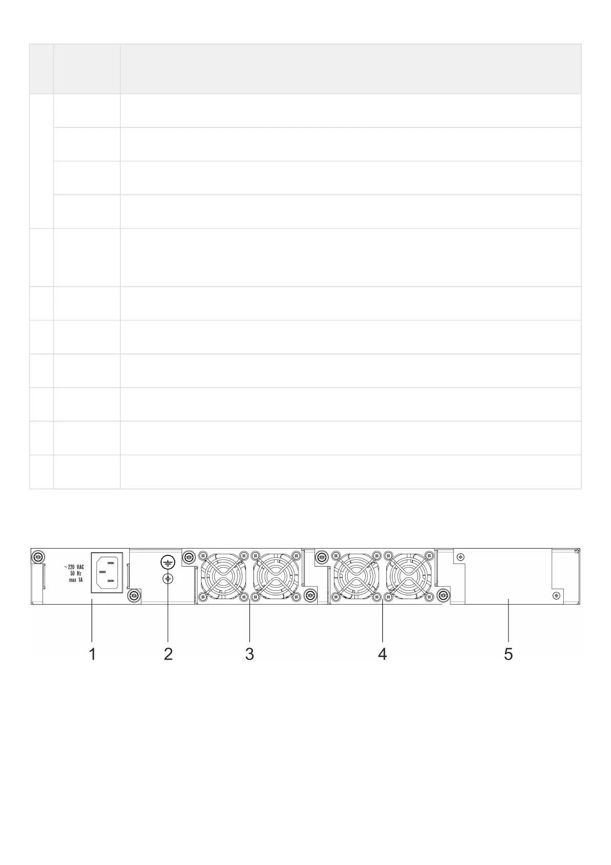
ESR-3100 rear panel
The rear panel of ESR-3100 is depicted in the figure below.
Figure 6 – ESR-3100 rear panel
Table 12 lists rear panel connectors of the router.
 Loading...