ESR series service routers.ESR-Series. User manual
ESR-3200 side panels
The side panel layout of ESR-3200 is depicted in figures 3 and 4.
Figure 3 – ESR-3200 right side panel
Figure 4 – ESR-3200 left side panel
Side panels of the device have air vents for heat removal. Do not block air vents. This may cause the
components to overheat, which may result in device malfunction. For recommendations on device
installation,see section Installation and connection.
2.4.2 ESR-3100 design
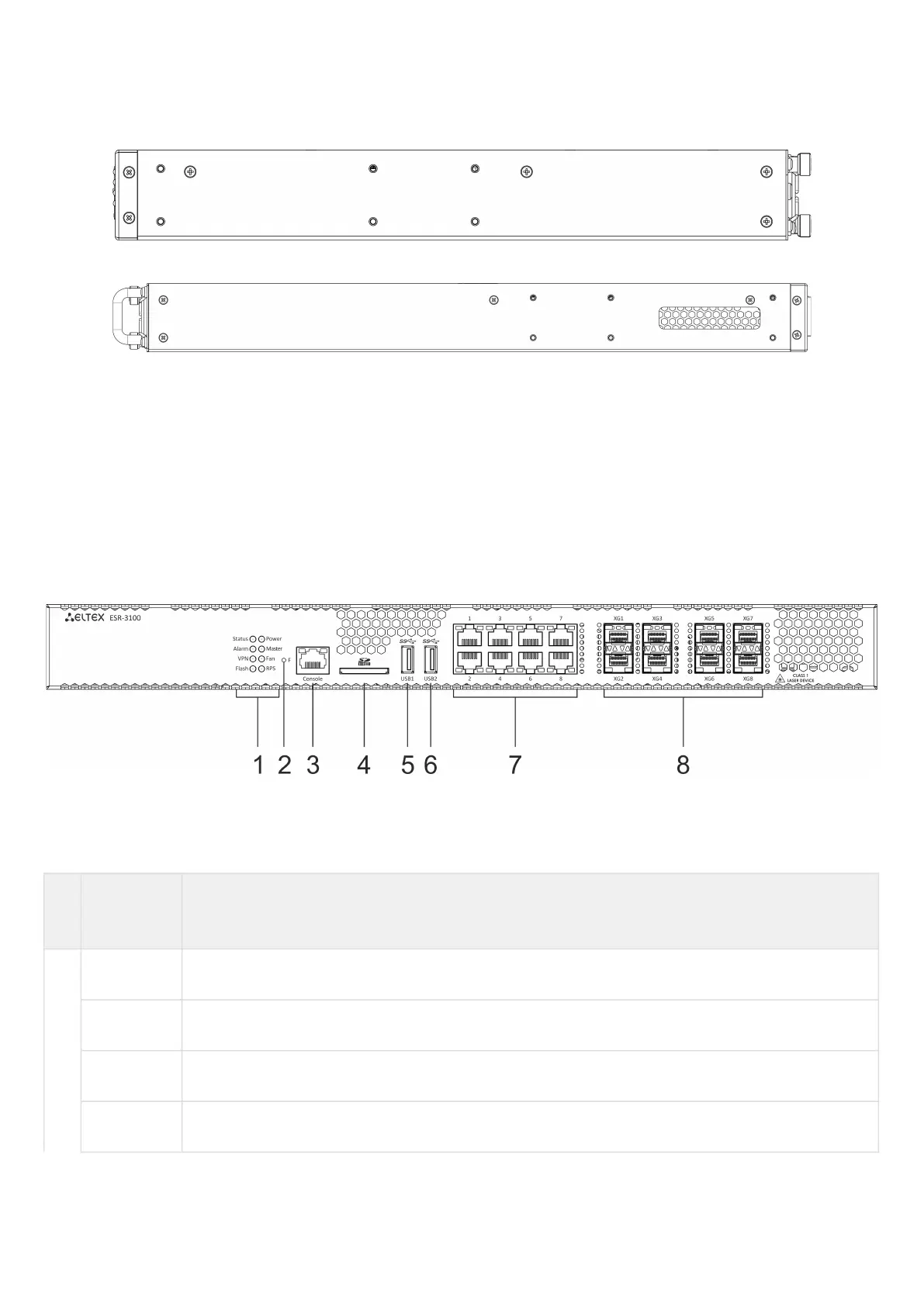
ESR-3100 front panel
The front panel layout is depicted in 5.
Figure 5 – ESR-3100 front panel
Table 11 lists connectors, LEDs and controls located on the front panel of ESR-3100.
Table 11 – Description of connectors, LEDs and controls located on ESR-3100 front panel
№ Front panel
element
Description
1 Status Current device status LED.
Alarm Alarm LED.
VPN VPN gateway operation mode LED.
Flash Activity of exchange with data storage – SD card or USB Flash.
 Loading...