ESR series service routers.ESR-Series. User manual
•
•
2.4 Design
This section describes the design of the device. Depicted front, rear, and side panels of the device, connectors,
LED indicators and controls.
The device has a metal-enclosed design for 1U 19" racks; housing size is 1U.
2.4.1 ESR-3200 design
ESR-3200 front panel
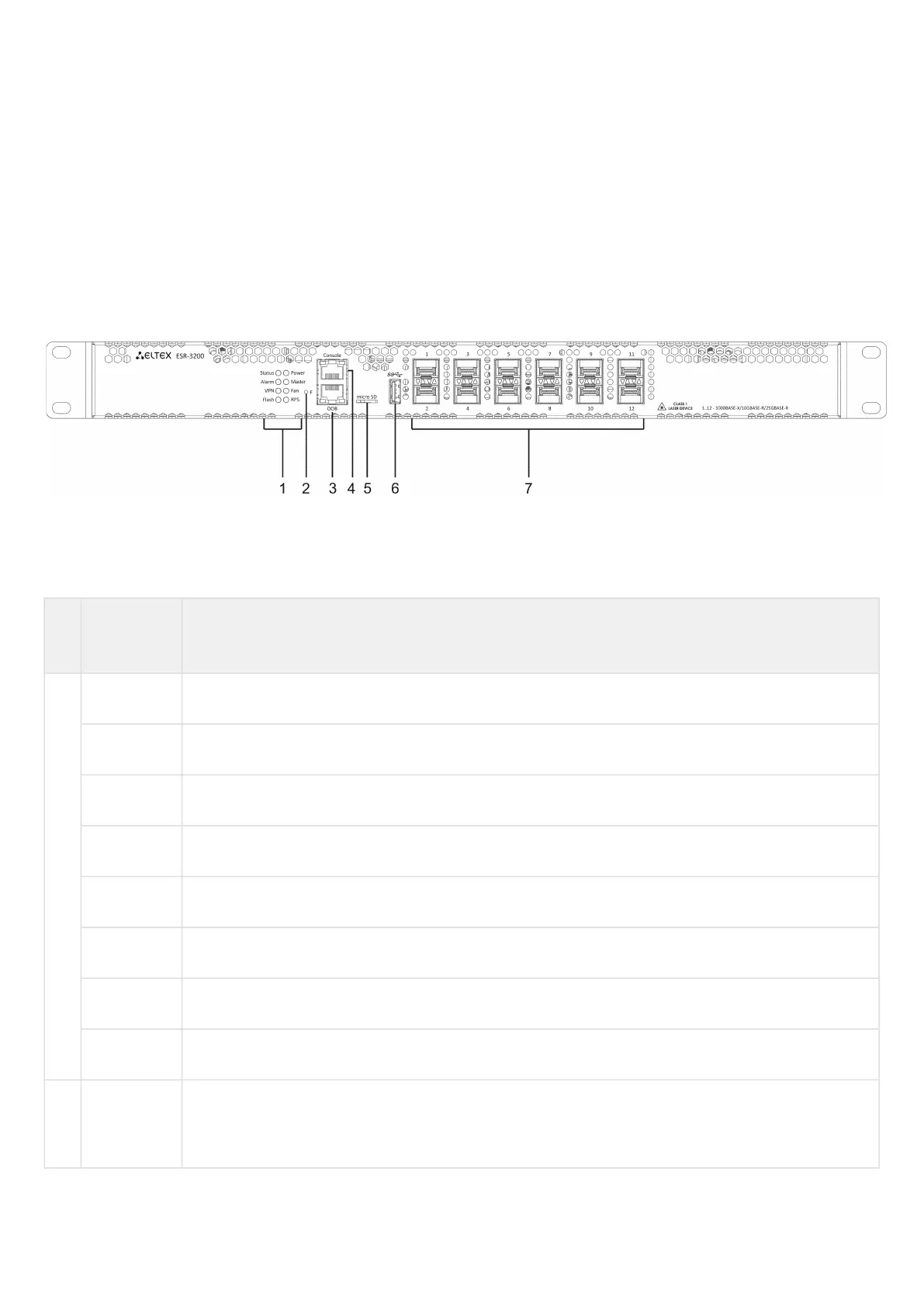
The front panel layout is depicted in Figure 1.
Figure 1 – ESR-3200 front panel
Table 9 lists connectors, LEDs and controls located on the front panel of ESR-3100.
Table 9 – Description of connectors, LEDs and controls located on ESR-3100 front panel
№ Front panel
element
Description
1 Status Current device status LED.
Alarm Alarm LED.
VPN VPN gateway operation mode LED.
Flash Activity of exchange with data storage – SD card or USB Flash.
Power Device power LED.
Master Failover mode operation LED (is not supported in the current version).
Fan Fan operation LED.
RPS Redundant power supply LED.
2 F Functional key that reboots the device and resets it to factory default configuration:
Pressing the key for less than 10 seconds reboots the device;
Pressing the key for more than 10 seconds resets the terminal to factory settings.
 Loading...