ESR series service routers.ESR-Series. User manual
ESR-12VF, ESR-14VF side panels
The side panel layout of ESR-12VF, ESR-14VF is depicted in Figures 41 and 42.
Figure 41 – ESR-12VF, ESR-14VF left side panel
Figure 42 – ESR-12VF, ESR-14VF right side panel
Side panels of the device have air vents for heat removal. Do not block air vents. This may cause the
components to overheat, which may result in device malfunction. For recommendations on device installation,
see section Installation and connection.
2.4.11 ESR-12V design
The device has a metal-enclosed design for 1U 19" racks.
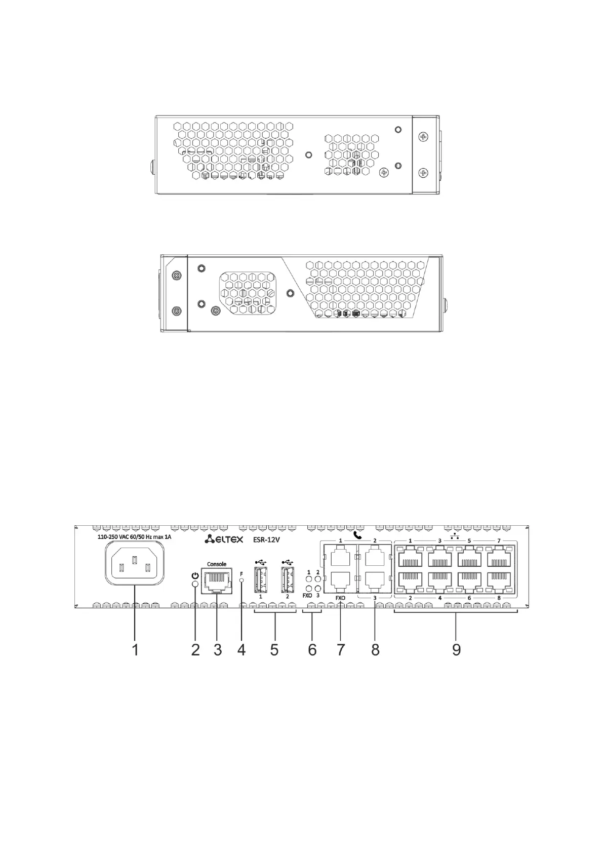
ESR-12V front panel
The front panel layout is depicted in figure 43.
Figure 43 – ESR-12V front panel
Table 32 lists connectors, LEDs and controls located on the front panel of ESR-12VF router.
 Loading...