ESR series service routers.ESR-Series. User manual
№ Front
panel
element
Description
FXS 1, FXS
2, FXS 3
4 connectors for internal subscriber terminals (for ESR-14VF).
9 [1 .. 8] 8 ports of Gigabit Ethernet 10/100/1000BASE-T (RJ-45).
10 Optical Port 1 port of Gigabit Ethernet-100/1000BASE-X (SFP).
11 1,2 Optical interfaces LED.
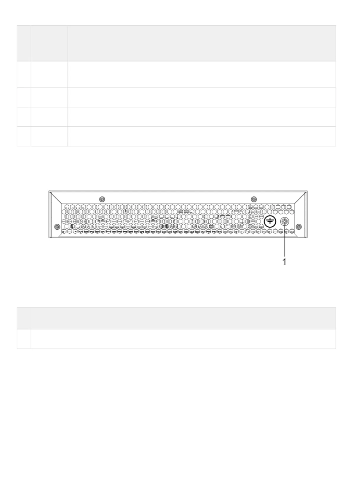
ESR-14VF, ESR-12VF rear panel
The rear panel layout of ESR-12VF, ESR-14-VF is depicted in figure 40.
Figure 40 – ESR-12VF, ESR-14VF rear panel
Table 31 lists rear panel connectors of the router.
Table 31 – Rear panel connectors description
№ Description
1 Earth bonding point of the device.
 Loading...