ESR series service routers.ESR-Series. User manual
2.4.10 ESR-14VF, ESR-12VF design
The device has a metal-enclosed design for 1U 19" racks.
ESR-14VF, ESR-12VF front panel
The front panel layout is depicted in figure 39.
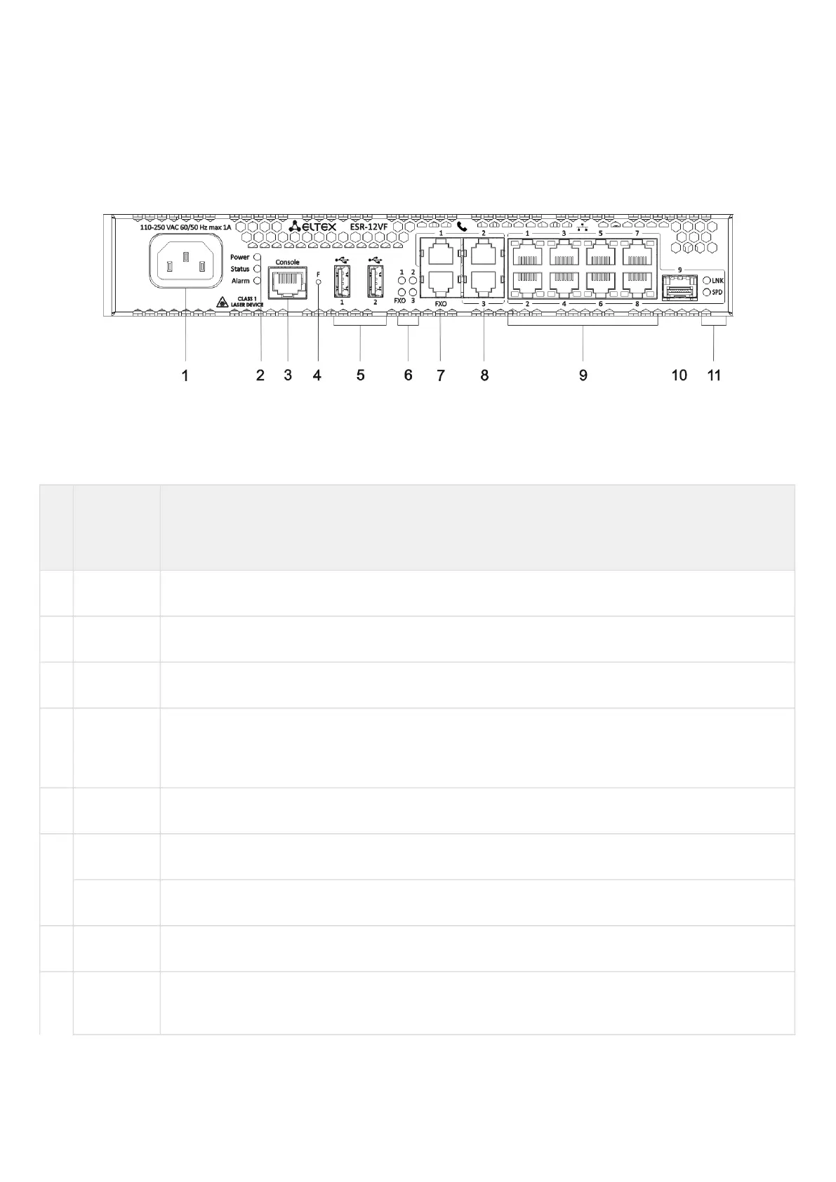
Figure 39 – ESR-14VF, ESR-12VF front panel
Table 30 lists connectors, LEDs and controls located on the front panel of ESR-14VF and ESR-12VF routers.
Table 30 – Description of connectors, LEDs and controls located on ESR-14VF, ESR-12VF front panel
№ Front
panel
element
Description
1 220V AC Power supply.
2 Power Device power LED.
3 Console Console port RS-232 (RJ-45) for local management of the device.
4 F Functional key that reboots the device and resets it to factory default configuration: - pressing the
key for less than 10 seconds reboots the device. – pressing the key for more than 10 seconds
resets the device to factory default configuration.
5 USB1, USB2 2 USB connectors for connecting external USB devices.
6 FXO PSTN external subscriber line LED.
1,2,3 Internal subscriber terminals LED.
7 FXO 1 FXO connector for connection PSTN external subscriber line (only for ESR-12VF).
8 FXS 1, FXS
2, FXS 3
3 connectors for internal subscriber terminals (for ESR-12VF).
 Loading...