ESR series service routers.ESR-Series. User manual
№ Front panel element Description
9 [1 .. 8] 8 ports of Gigabit Ethernet 10/100/1000BASE-T (RJ-45)
10 Optical Port 4 ports of Gigabit Ethernet 10/100/1000BASE-X (SFP)
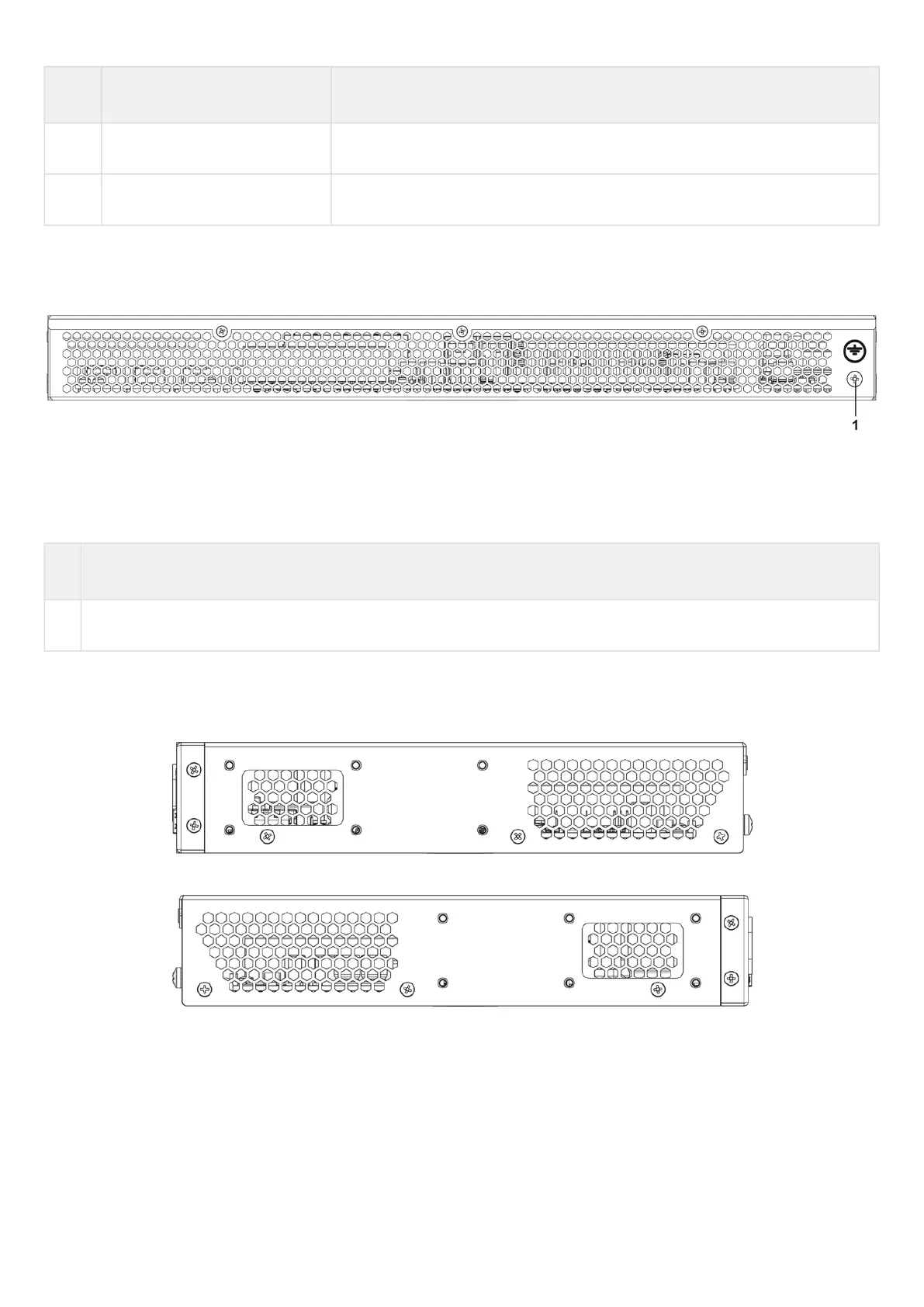
ESR-21 rear panel
The rear panel layout of ESR-21 is depicted in figure 29.
Figure 29 – ESR-21 rear panel
Table 24 lists rear panel connectors of the router.
Table 24 – Rear panel connectors description
№ Description
1 Earth bonding point of the device.
ESR-21 side panels
The side panel layout of ESR-21 is depicted in figures 30 and 31.
Figure 30 – ESR-21 left side panel
Figure 31 – ESR-21 right side panel
Side panels of the device have air vents for heat removal. Do not block air vents. This may cause the
components to overheat, which may result in device malfunction. For recommendations on device installation,
see section Installation and connection.
 Loading...