ESR series service routers.ESR-Series. User manual
Indicator name Indicator function LED State Device State
Power Device power LED. Green Device power is normal. Main
power supply, if installed, is
operational.
Orange Main power supply failure, fault,
or the primary network is
missing.
Off Device internal power supply
failure.
Master Indicator of failover modes
operation.
- -
Fan Cooling fan status. Off All fans are operational.
Red One or more fans has failed.
Possible cause of failure: at least
one of the fans has stopped or is
working at lower rpm.
RPS Backup power supply
operation mode.
Green Backup power supply is installed
and operational.
Off Backup power supply is not
installed.
Red Backup power supply is missing
or failed.
ESR-3200, ESR-3100, ESR-1511, ESR-1500 light indication
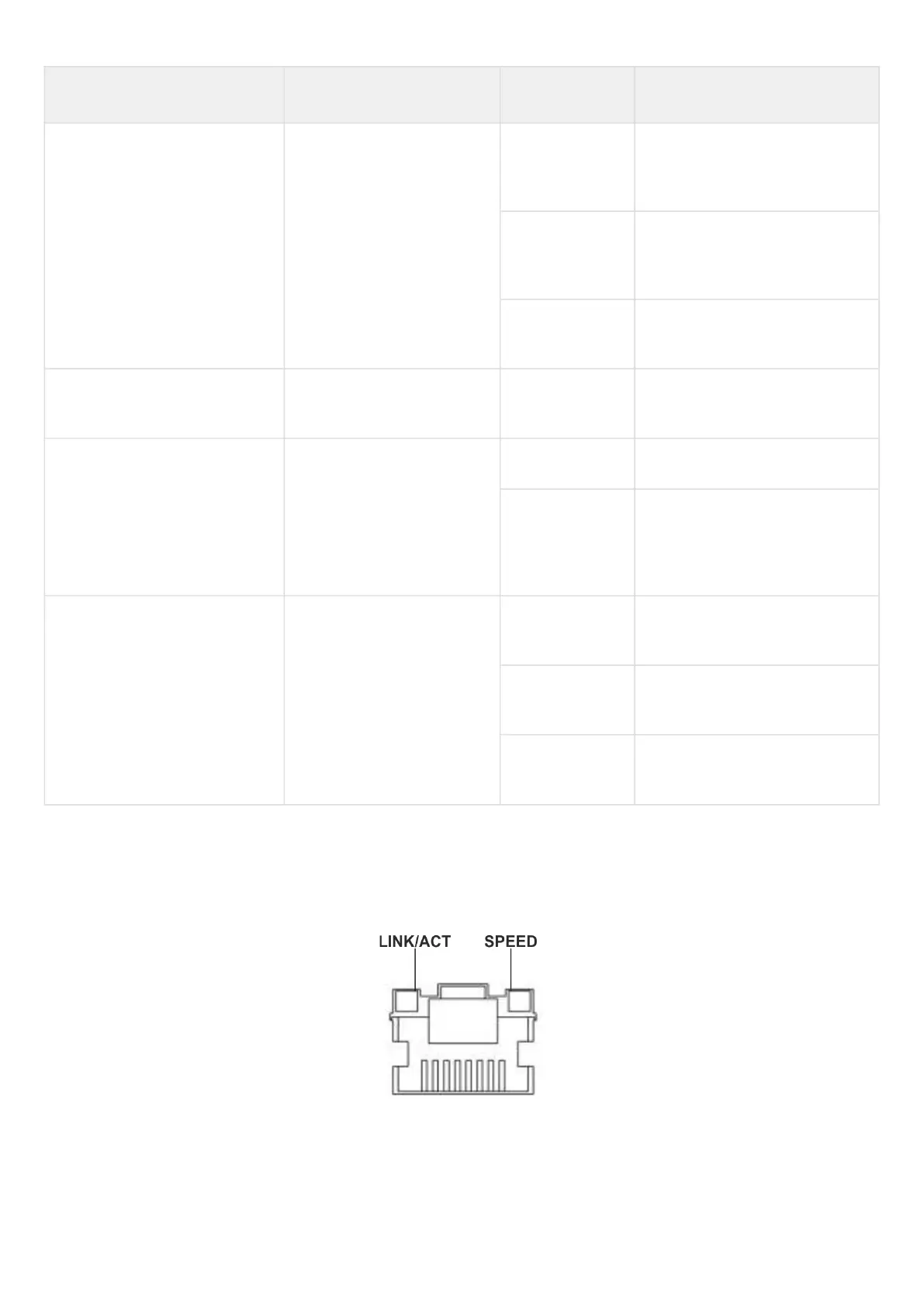
Gigabit Ethernet copper interface and SFP interface statuses are represented by two LEDs – green LINK/ACT
LED and amber SPEED LED. Location of the copper interface LEDs is depicted in figure 52. SFP interface
status is depicted in figure 53. For light indication meaning, see Tables 40 and 41 respectively.
Figure 52 – Location of RJ-45 connector indicators
 Loading...