ESR series service routers.ESR-Series. User manual
ESR-200/ESR-100 light indication
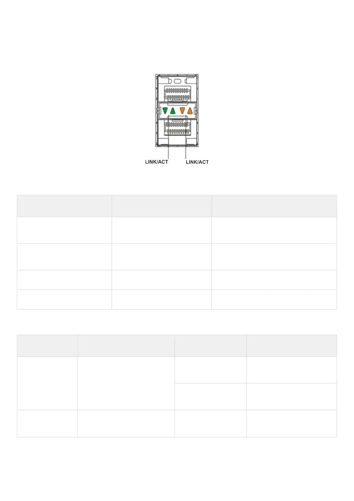
Gigabit Ethernet copper interface and SFP interface statuses are represented by two LEDs – green LINK/ACT
LED and amber SPEED LED. Location of the copper interface LEDs is depicted in figure 50. SFP interface
status is depicted in figure 54. For light indication meaning, see Table 43.
Figure 54 – Location of optical interface indicators
Table 43 – Light indication of copper and SFP interfaces status
SPEED indicator is lit LINK/ACT indicator is lit Ethernet interface state
Off Off The port is disabled or connection is not
established.
Off Solid on 10 Mbps or 100 Mbps connection is
established.
Solid on Solid on 1000 Mbps connection is established.
X Flashes Data transfer is in progress.
The following table describes the states of the system LEDs on the device and their meanings.
Table 44 – Status of system indicators
Indicator name Indicator function LED State Device State
Status Current device status LED. Green Device is in normal operation
state.
Red Device is booting up the
software.
Alarm Device alarm presence and level
indicator
1
.
- -
 Loading...