EPSON Stylus COLOR 3000
EPSON Stylus Color 3000 Service Manual
-31
EMINDER
Do not touch the printhead surface in the removed CR unit. Avoid static electricity
discharges when handling the printhead; it is directly attached to the printhead driver circuit.
Pay attention to the oil pad when removing the CR guide shaft from the CR unit, since it is
easily dislocated.
When installing the CR guide shaft in the printer mechanism, fit the PG adjust lever into the
cutout on the right frame (See Figure 3-27).
REQUIRED ADJUSTMENT
After reinstalling the CR unit or parallelism adjustment bushings, perform the following:
PG adjustment
Bi-D adjustment
Uni-D adjustment
(See Chapter 4.)
If you replace the printhead along with the CR unit, be sure to write new printhead voltage
data to the EEPROM (See Chapter 4).
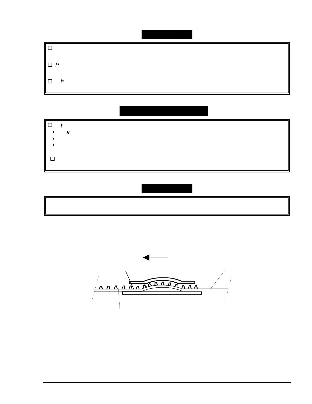
EMINDER
When attaching the timing belt to the CR unit, note the two parts on the belt: flat and toothed.
Be sure to position the two parts carefully, as shown in Figure 3-28.
CR Motor Assembly Side
Timing Belt
Flat Part
Toothed Part
Figure 3-28. Timing Belt Installation

 Loading...


