EPSON Stylus COLOR 3000
EPSON Stylus Color 3000 Service Manual
-23
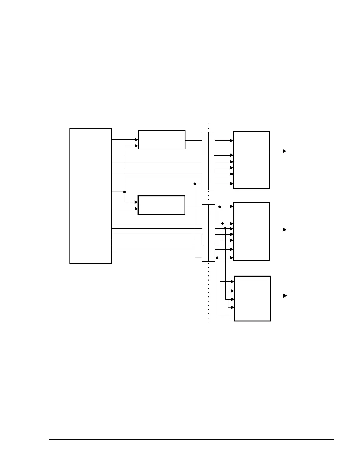
Printhead Driver Circuit
This printer has two separate printhead driver circuits for the black and color printheads. Each circuit has a
common voltage driver circuit attached to the circuit control board, and a nozzle selector circuit attached to
the printhead. Each of the black and color common driver circuits is composed of a hybrid IC H8D2813E
(IC22) and a terminal transistor. The black printhead nozzle selector circuit is composed of a 128-bit transfer
gate array IC IR2C72C, and the color printhead nozzle selector circuit consists of a 128-bit transfer gate
array IC IR2C72C (for cyan and yellow) and a 64-bit transfer gate array IC IR2C73C (for magenta). Printing
data is separated into common voltage signals and nozzle selection signals at the gate array E05B33 (IC6)
and is then transferred to the corresponding circuits. Figure 2-20 shows the printhead driver circuit block
diagram.
E05B33 (IC6)
COM
IR2C72C
CN13
LAT
CLK
SI
COM
CN12
LAT
CLK
Magenta
Cyan
Yellow
NCHG
LAT
CLK
S2
IR2C72C
IR2C73C
VHPR
VHV
SCLK,SSTB,SCLR
S3
S1
COM
NCHG
VHV
VHV
Common Driver
Common Driver
C203 Main Control Circuit Board Printhead Boards
Black
BHCLK
BHLAT
BA/BBHDATA
BHNCHG
BCHG,BKC
BND0/1,BMD0/1
SBDATA
CCHG,CKC
CND1/2,CMD1/2
SCDATA
CHCLK
CHLAT
YHDATA
CHDATA
MHDATA
CHNCHG
(IC 22)
(IC 22)
Figure 2-20. Printhead Driver Circuit Block Diagram

 Loading...


