EPSON Stylus COLOR 3000
EPSON Stylus Color 3000 Service Manual
-11
REQUIRED ADJUSTMENT
After replacing the printer mechanism, perform all required adjustments to write appropriate
values such as printhead data into the EEPROM on the main control board (See Chapter 4).
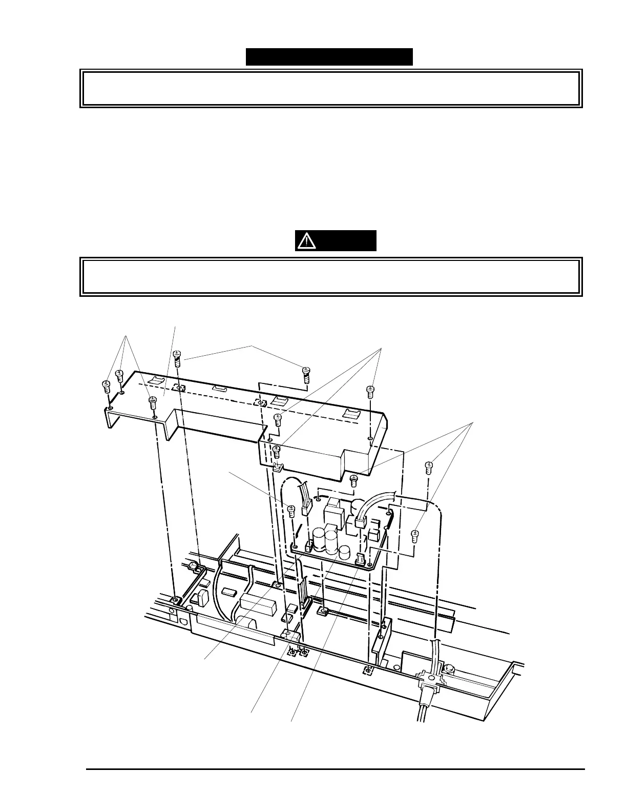
PSB/PSE Board Removal
1. Remove the upper housing (See page 3-4).
2. Remove the printer mechanism (See page 3-10).
3. Remove eight screws (six CBS screws, 3×8 and two CBP screws, 3×12) securing the upper shield plate
to the lower housing.
4. Disconnect the power cable and connector cable for the main board from CN1 and CN2, respectively.
5. Remove four screws (CBS, 3×6) securing the PSB/PSE board to the lower housing, then remove the
PSB/PSE board.
WARNING
Do not disconnect the cable from CN1 for at least 5 minutes after disconnecting the power cable
from the AC socket; the capacitor on the C172 PSB/PSE board is still discharging electricity.
CBS Screws (3×8)
Upper Shield Plate
CBP Screws (3×12)
CN2
PSB/PSE Board Assembly
CN1
CBS Screws (3×8)
CBS Screws (3×6)
CBS Screw (3×6)
Figure 3-9. PSB/PSE Board Removal

 Loading...


