Disassembly and Assembly
3-10 EPSON Stylus Color 3000 Service Manual
Printer Mechanism Removal
1. Remove the upper housing. (See page 3-4).
2. Disconnect the following connector cables from the connectors on the main board:
CN3 CN4 CN 5 CN6 CN7 CN10 CN11 CN12
CN13 CN14 CN18 CN20 CN21 CN22 CN23
3. Disconnect the ASF PW sensor connector cable from the PW sensor connector on the left edge guide of
the ASF.
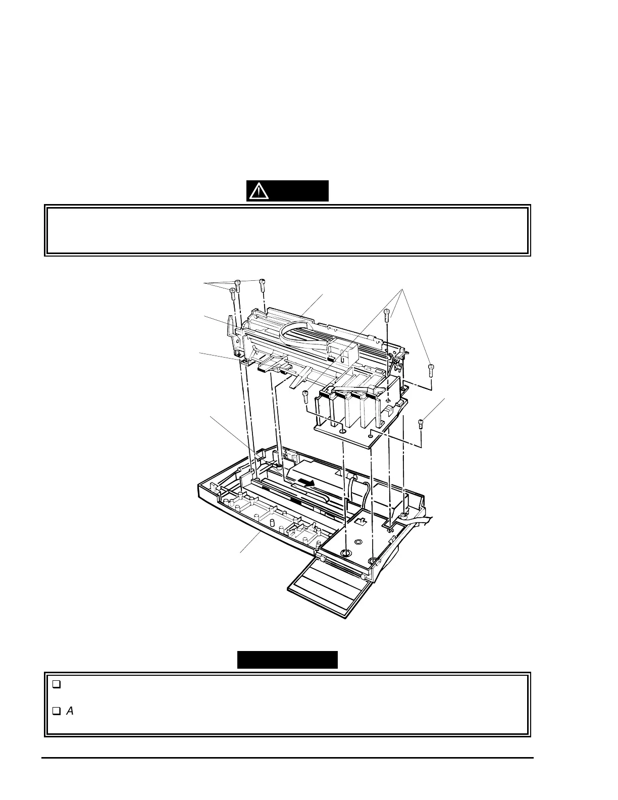
4. Remove seven screws (six CB screws, 4×14 and one CBP screw, 3×8) securing the printer mechanism to
the lower housing.
The connectors for the motor (CN20, 22 and 23) and for the ink cartridges (CN7, 12, 13 and
14) look similar. Be sure to connect them properly; inappropriate connections may result in a
malfunction of the PSE/PSB board or the main control board.
REMINDER
Lubricate the top surface of the paper eject frame in an ASF printer mechanism, since the
CR unit slides along a non-lubricated frame.
After installing the printer mechanism, insert the waste ink draining tubes leading into the
sub waste ink drain pads (See page 3-23).
CAUTION
CB Screws (4×14)
ASF PW Sensor
Connector Cable
Lower Housing
CBP Screw (3×8)
CB Screws (4×14)
Printer Mechanism
ASF PW Sensor
Paper Eject Frame
Figure 3-8. Printer Mechanism Removal

 Loading...


