EPSON Stylus COLOR 3000
EPSON Stylus Color 3000 Service Manual
-21
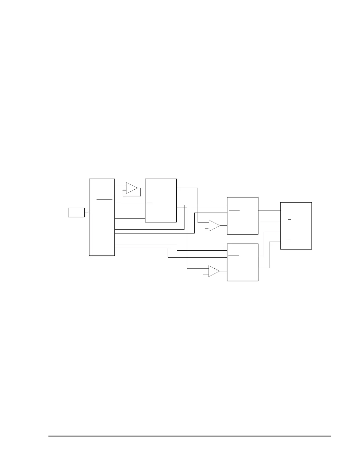
CR Motor Driver Circuits
The gate array E05B45 produces phase data (CRDA0-5) for the CR motor and sends it to the 2-channel D/A
converter in parallel data. When the phase-change trigger signal (CRTRG) is sent from the CPU to the gate
array, the A/B phase-change signal (CRDASEL) is output. Then, A- and B-phase-data are transferred to
channels A and B in the D/A converter, respectively. The transferred data for the 2 phases is converted into
analog data in the converter to be transferred to the CR motor driver ICs (IC19 and IC20), where the phase
excitation current is determined for each micro step of the motor. The 4-phase motor enables the minimum
micro step (0.013 mm/step) with the driven 4W1-2 phase. The gate array E05B45 (IC16) sends phase data
(PHASEA/B, ENAN/ENBN) directly to the CR motor driver ICs A3953 (IC19 and IC20) to control the
excitation mode and the amount and direction of motor rotation.
While the CR is in the home position or the printer is in ink cartridge replacement mode, the 2-2 phase is
driven in the low current holding mode to stop the motor. Figure 2-18 shows the CR motor driver circuit block
diagram.
GA
E05B45
(IC16)
CR Motor
CR B
PHASEA
ENABLE
OUTA
OUTB
REF
PHASEB
ENABLE
OUTA
OUTB
REF
RFBA
OUTA
RFBB
OUTB
WR
A/B
DB0-7
CRV
CRDALD
CRDASEL
CRDA0-5
PHASEA
ENAN
PHASEB
ENBN
CR Motor Driver ICs
A3953 (IC19,20)
D/A Converter
(IC25)
CRTRG
CPU
CR A
CR A
CR B
Figure 2-18. CR Motor Block Diagram

 Loading...


