EPSON Stylus COLOR 3000
EPSON Stylus Color 3000 Service Manual
-15
C203 Main Control Board
This printer uses C203 Main for the main control circuit board. It consists of the following:
16-bit CPU H8S/2655 (IC5) Runs at 19.66 MHz.
2 gate arrays E05B33 (IC6) Manages interfaces, motors, and printheads.
E05B45 (IC16)
P-ROM, DRAM and MROM
Drivers Produces common voltage for printheads.
Drives motors.
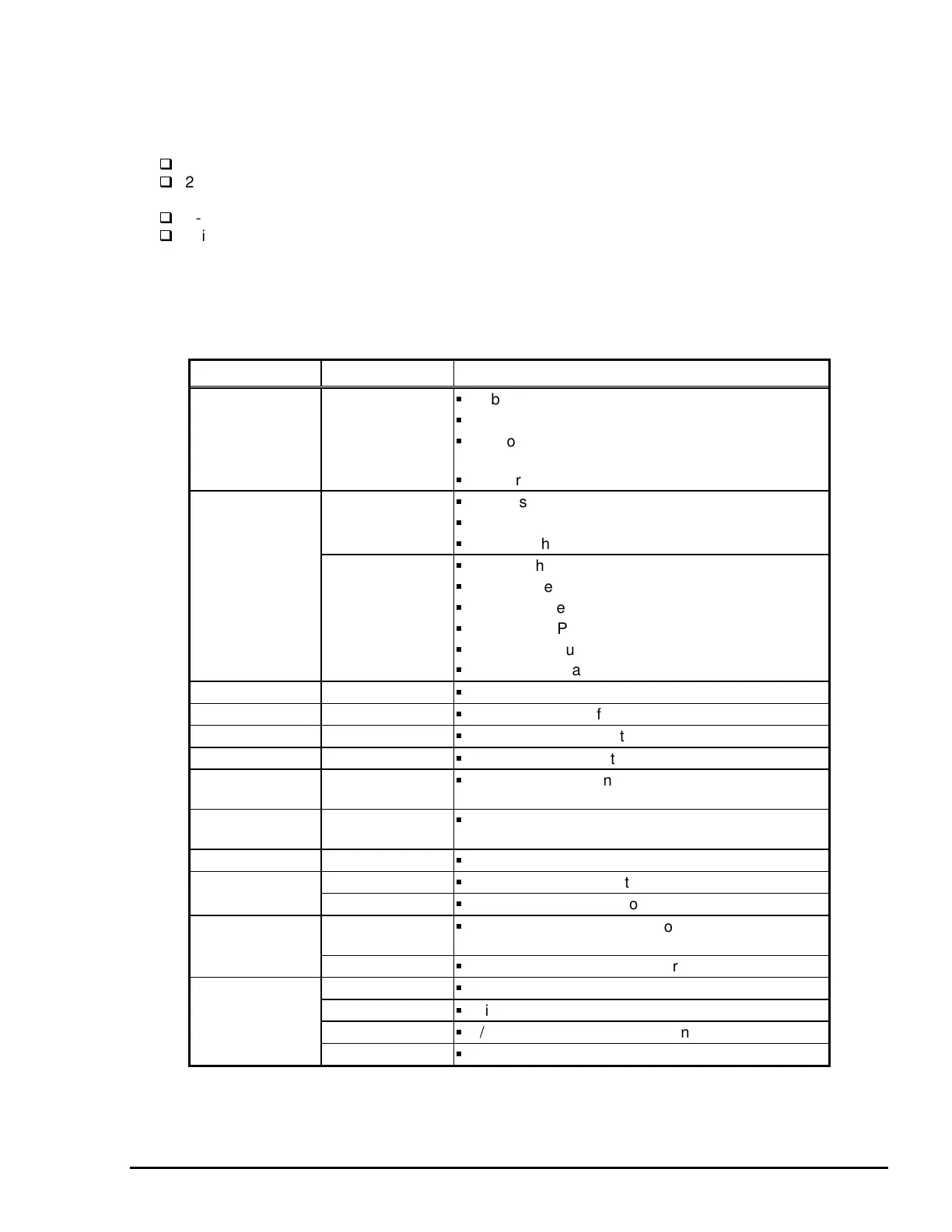
Table 2-8 shows the allocated functions for major components. Figure 2-15 shows the main control circuit
block diagram.
IC Location Function
CPU IC5
16-bit CPU.
Runs at 19.66 MHz.
Controls the printer at the gate arrays IC5 and IC6
according to the program in P-ROM.
Monitors the printhead temperature.
Gate Array IC16
Controls the I/F for the control panel.
Controls the CR motor.
Manages the sensors.
IC6
Controls the parallel I/F.
Controls the serial I/F.
Controls Type-B I/F.
Controls the PF motor.
Controls the pump motor.
Controls black and color printheads.
DRAM IC12
Manages buffers, work area in the CPU.
SRAM IC14, IC28
Manages input buffer.
C.G. ROM IC11
Manages CG (Character Generator).
P-ROM IC13
Manages printer control program.
Optional ROM
IC7, IC10
For optional fonts and CG (not attached as a
standard item.)
EEPROM IC1
Stores values for the default settings and other
values.
Timer counter IC IC2
Manages timers for the ink system.
Reset IC IC9
Outputs a reset signal to the logic line (+5V).
IC3
Outputs a reset signal to the power line (+42V).
Common driver
IC
IC22
Produces common voltage for the black printhead.
IC23
Produces common voltage for the color printhead.
Driver IC17
Drives the PF motor.
IC18
Drives the pump motor.
IC25
D/A converter for CR motor control.
IC19, IC20
Drives the CR motor.
Table 2-8. Location and Functions of Major Components

 Loading...


