Disassembly and Assembly
3-30 EPSON Stylus Color 3000 Service Manual
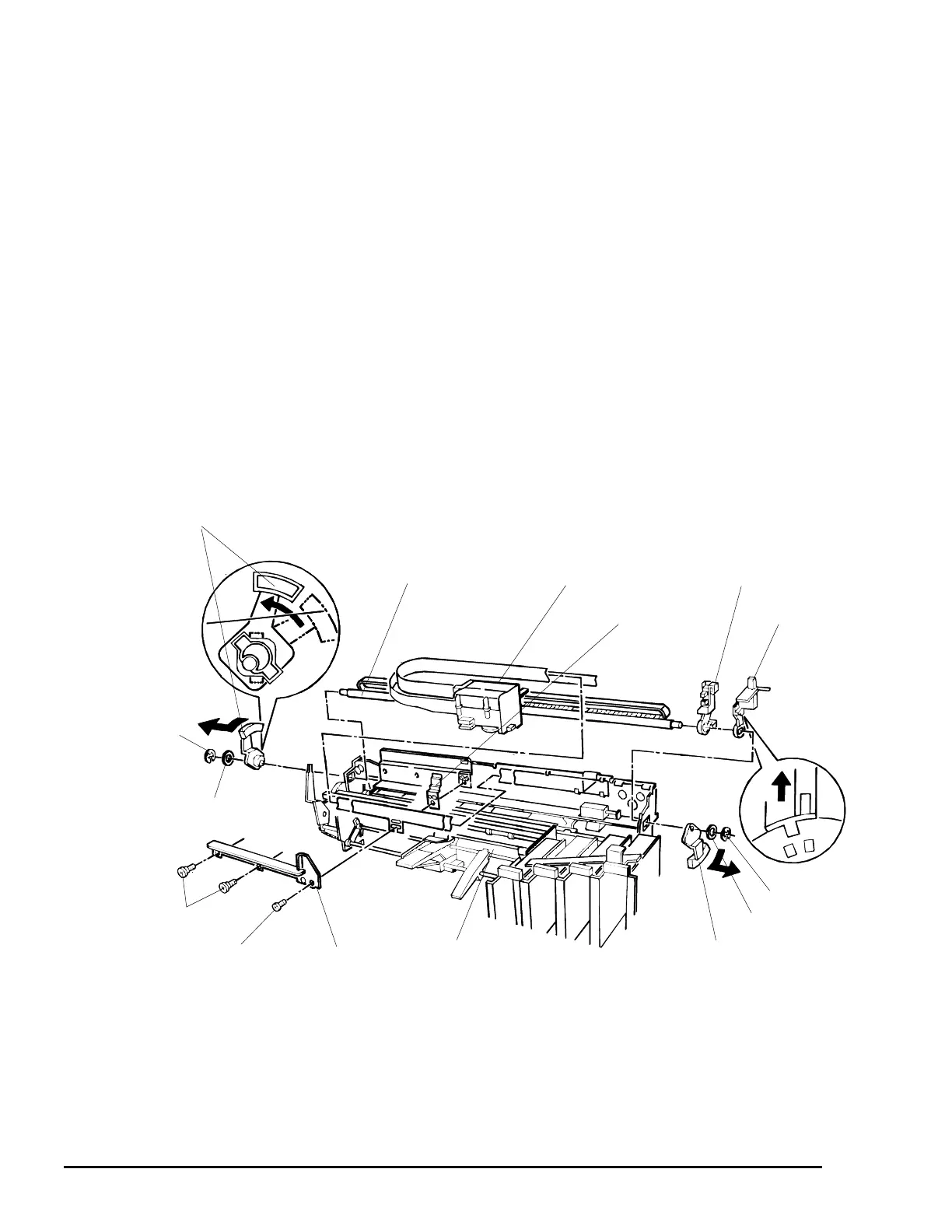
CR Unit Removal
1. Remove the upper housing (See page 3-4).
2. Remove the printer mechanism (See page 3-10).
3. Disconnect the connector cable from the HP sensor.
4. Remove the belt tension spring to loosen the timing belt.
5. Disengage the timing belt from the pulley on the CR motor and the sub pulley.
6. Remove one E-ring and one plain washer (6×0.7×12) from each end of the CR guide shaft.
7. If the head cleaner lever (See Figure 3-20) is locking the CR unit, push the lever down manually to unlock
the CR unit.
8. Remove one screw (CBS, 3×6) and two CR mounting shafts securing the black and color cables with the
printhead cable guide to the base frame. Then remove the printhead cable guide and tube mounting
plate, and remove the ink tubes from the printer mechanism.
9. Release the coupling screws connecting the rigid ink tubes to the flexible ink tube bundle. Then remove
the flexible tubes.
10. Turn the parallelism adjustment bushings joining the CR guide shaft to the right and left frame assemblies
and release the bushings. Then remove the CR unit along with the CR guide shaft.
11. Remove the CR guide shaft from the CR unit.
arallelism Adjustment Bushing
E-ring
Plain Washer (6×0.7×12)
PG Adjust Lever
HP Sensor Holder
Parallelism Adjustment Bushings
E-ring
Plain Washer (6×0.7×12)
CR Guide Shaft
CBS Screw (3×6)
CR Unit
Tube Mounting Plate
Printer Mechanism
Printhead Cable
Guide
CR Mounting Shafts
Figure 3-27. CR Unit Removal

 Loading...


