EPSON Stylus COLOR 3000
EPSON Stylus Color 3000 Service Manual
-1
5.1 General Description
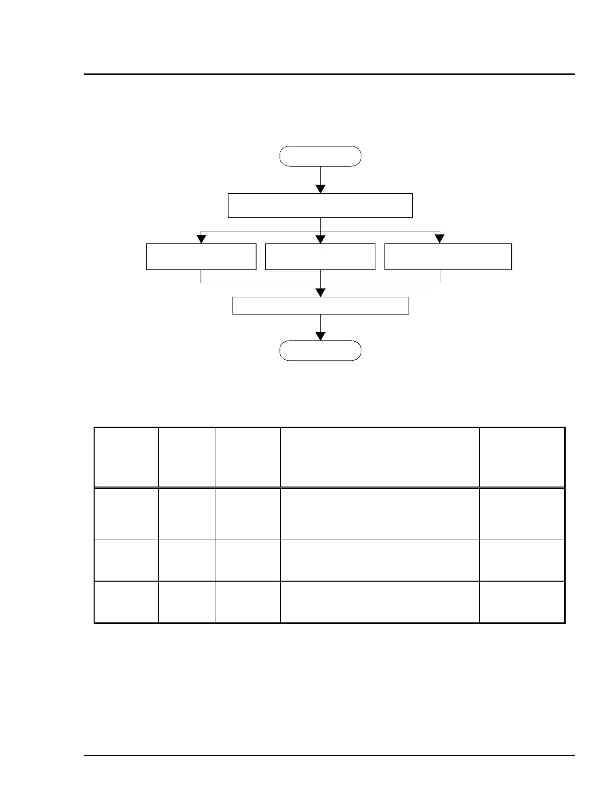
This section describes procedures for isolating printer failures at two levels; unit level troubleshooting and
component level troubleshooting. Refer to the flowchart below to isolate the defective unit and perform
repairs at the component level. Tables 5-1, 5-2, and 5-3 show the coil resistance for the motors, sensor
status and error codes, and error conditions, respectively.
Table 5-1 Motor Coil Resistance
Motor
Connector
No.
Test pin No.
Test method
(Set the multimeter to Ohms. Unplug the
power cable from the AC inlet and
disconnect the harnesses from the main
board.)
Meter reading
(at 77°F (25°C)
per phase)
CR
(Carriage)
Motor
CN22
Pins 1 and 2
or
Pins 3 and 4
Place one lead to Pin 1 and the other to Pin
2 and check the coil resistance per phase.
Repeat for Pins 3 and 4.
5 Ω ± 7 %
Pump Motor CN20
Pins 1 and 2
or
Pins 3 and 4
Place one lead to Pin 1 and the other to Pin
2 and check the coil resistance per phase.
Repeat for Pins 3 and 4.
7.7 Ω ± 10 %
PF (Paper
Feed) Motor
CN23
Pins 1 and 3
or
Pins 2 and 4
Place one lead to Pin 1 and the other to Pin
2 and check the coil resistance per phase.
Repeat for Pins 3 and 4.
10 Ω ±10 %
START
Unit-level Troubleshooting
Unit Repair
(C172 PSB/PSE board) (C203 MAIN board) (M-4J60 printer mechanism)
Disassembly, Assembly and Adjustment
END
Unit Repair Unit Repair
Figure 5-1. Troubleshooting Flowchart

 Loading...


