Troubleshooting
EPSON Stylus Color 3000 Service Manual
5-2
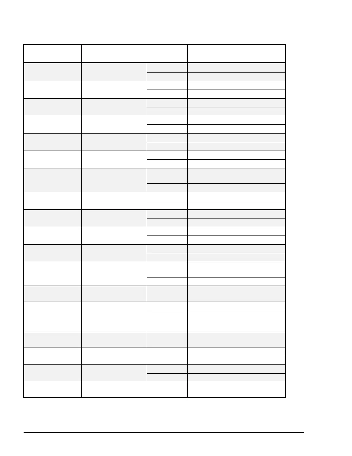
Table 5-2. Sensor Status
Sensor
Connector No.
Test pin No.
Signal level Detected condition
HP Sensor CN6
Closed
∗
At the Home Position
Pins 1 and 3 Open
†
Not at the Home Position
Rear PE Sensor CN5 HIGH Paper loaded
Pins 1 and 2 LOW No paper loaded
Front PE Sensor CN4 HIGH Paper loaded
Pins 1 and 2 LOW No paper loaded
Release Sensor CN3 HIGH Tractor feed mode
Pins 1 and 2 LOW Friction feed mode
Black Ink Cartridge CN14 HIGH No black ink cartridge installed
Sensor Pins 1 and 2 LOW Black ink cartridge installed
Cyan Ink Cartridge CN13 HIGH No cyan ink cartridge installed
Sensor Pins 1 and 2 LOW Cyan ink cartridge installed
Magenta Ink
Cartridge
CN7 HIGH No magenta ink cartridge installed
Sensor Pins 1 and 2 LOW Magenta ink cartridge installed
Yellow Ink Cartridge CN12 HIGH No yellow ink cartridge installed
Sensor Pins 1 and 2 LOW Yellow ink cartridge installed
Black Ink End Sensor CN14 HIGH Black Ink end
Pins 3 and 4 LOW Black Ink remaining
Cyan Ink End Sensor CN13 HIGH Cyan Ink out
Pins 3 and 4 LOW Cyan Ink remaining
Magenta Ink End CN7 HIGH Magenta Ink out
Sensor Pins 3 and 4 LOW Magenta Ink remaining
Yellow Ink End
Sensor
CN12 HIGH Yellow Ink out
Pins 3 and 4 LOW Yellow Ink remaining
ASF PW Sensor
CN8
Pins 2 and 4
Analog data
Maximum 10kΩ
ASF PL Sensor CN11 HIGH Not set
Pins 1 and 2,
Pins 3 and 4,
Pins 5 and 6
LOW Set
ASF PQ Sensor
CN10
Pins 3 and 2
Analog data
Maximum 10kΩ
Platen Gap Sensor CN9 HIGH Thick paper side (+)
Pins 1 and 2 LOW Thin paper side (-)
CR PW Sensor CN21 HIGH Paper detected
Pins 24 and 25 (GND) LOW No paper detected
Thermistor
CN18
Pin 2 and 3
Analog data
Maximum 10kΩ (at 24°C)
∗: When it is closed, the output voltage level is 2.5V or higher.
†: When it is open, the output voltage level is lower than 2.5V.

 Loading...


