Appendix
EPSON Stylus Color 3000 Service Manual
A-7
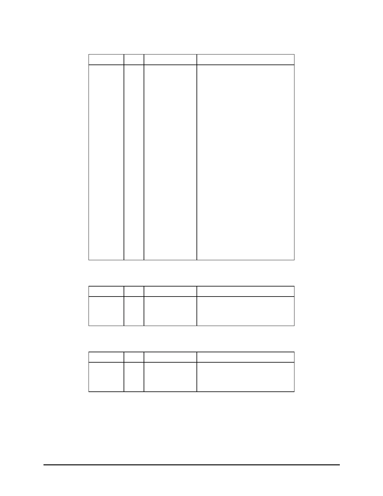
Pin No. I/O Signal Name Description
1
BCO
2 I THS Thermistor signal
3
GND Ground
4 O BHLAT Latch signal
5
GND Ground
6 O BSI 2 Data
7
GND Ground
8 O BSI 1 Data
9
GND Ground
10 O BHCLK Clock signal
11
GND Ground
12 O BHNCHG NCHG signal
13
GND Ground
14
+ 5 Power source
15
GND Ground
16
GND Ground
17
GND Ground
18 O COM Common output
19 O COM Common output
20 O COM Common output
21
VHPR Drive voltage
22
VHPR Drive voltage
23
NC
24 I CR_PW CR PW sensor signal
25
GND Ground
26
+ 5 Power source
Pin No. I/O Signal Name Description
1 O A Phase A output
2 O / A Phase/ A output
3 O B Phase B output
4 O / B Phase / B output
Pin No. I/O Signal Name Description
1 O A Phase A output
2 O / A Phase / A output
3 O B Phase B output
4 O / B Phase / B output
Table A-18. Connector Pin Assignments (CN21)
Table A-19. Connector Pin Assignments (CN22)
Table A-20. Connector Pin Assignments (CN23)

 Loading...


