EPSON Stylus COLOR 3000
EPSON Stylus Color 3000 Service Manual
-19
ASF_PL: Output from the PL (Paper Length) sensor.
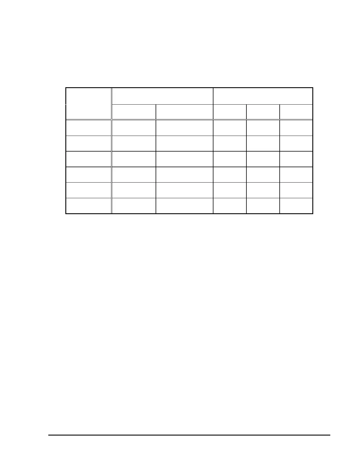
Paper length is determined by three mechanical switches that detect the paper length based on the rear
edge guide position and paper tray extension position. The state of the paper tray tells the printer the range
of paper size, as shown in Table 2-10. The paper size is determined and memorized by combining the paper
width and paper length detected by the ASF PW sensor and the PL sensor.
Paper tray condition Corresponding sensor
combination
Length Range
Rear edge
guide
Paper tray
extension
Switch 1 Switch 2 Switch 3
Up to 6.22 in.
(158 mm)
0 to 0.87 in.
(0 to 22 mm)
In On On Off
Up to 9.13 in.
(232 mm)
Up to 3.78 in.
(96 mm)
In On Off Off
Up to 10.24 in.
(260 mm)
Up to 4.92 in.
(125 mm)
In Off On Off
Up to 11.14 in.
(283 mm)
Up to 5.79 in.
(147 mm)
In Off Off Off
Up to 11.89 in.
(302 mm)
Up to 6.57 in.
(167 mm)
In Off On Off
Up to 24.53 in.
(623 mm)
Down
Pulled out more
than 0.20 in (5 mm)
On On On
ASF_PQ: Output from the PQ (Paper Quantity) sensor.
The paper quantity sensor uses a sliding potentiometer (maximum resistance: 10 ohms). The sensor,
attached to the right edge guide in the hopper, detects the paper quantity between a maximum of 0.59 in. (15
mm) and a minimum of 0.12 in. (3 mm). The detected quantity is converted into the corresponding
resistance and the information is transferred to the CPU's analog port. When the sensor detects the
condition of 3.6 mm, which is approximately 35 sheets of 20-lb. bond paper, it outputs the signal
PAPERLOW.
GAP: Output from the PG (Platen Gap) sensor.
The PG sensor determines whether the adjust lever is set to thin (0) or thick (+). The GAP signal is HIGH
when the lever is set to thick (+), and LOW when it is set to thin (0). This sensor uses a mechanical switch.
CR_PW: Output from the CR PW (Paper Width) sensor.
The CR PW sensor, attached to the left side of the CR unit, uses a photo interrupter system. While the CR
returns in paper width seek mode, the sensor reads the voltage level of output signals for each CR motor
phase pulse change. It uses this information to determine positions for both edges of the paper. This
operation prevents printing on the platen. If no changes are detected in paper size by the ASF PW sensor
and ASF PL sensor, the CR PW sensor is not activated. The signal output from this sensor is sent directly to
the analog port of the CPU.
Figure 2-17 shows the sensor circuit block diagram.
Table 2-10. Paper Length Detecting Range

 Loading...


