Operating Principles
EPSON Stylus Color 3000 Service Manual
2-18
Thermistor
The thermistor is attached to the color printhead and monitors temperatures around the printhead. This helps
avoid changes in ink viscosity that may affect printing results. The signal output from the sensor is directly
transmitted to the analog port of the CPU.
ASF_PW: Output from the ASF PW (Paper Width) sensor.
The ASF PW sensor uses a sliding potentiometer. The maximum resistance is 10kΩ. It is attached to the left
edge guide in the ASF hopper assembly. By aligning the left edge guide to the paper, the sensor actuator
runs along the grooves at the bottom of the stacker. The length measured by the actuator is converted into
ohms that correspond to the paper width. Then the value is transferred to the analog port of the CPU. The
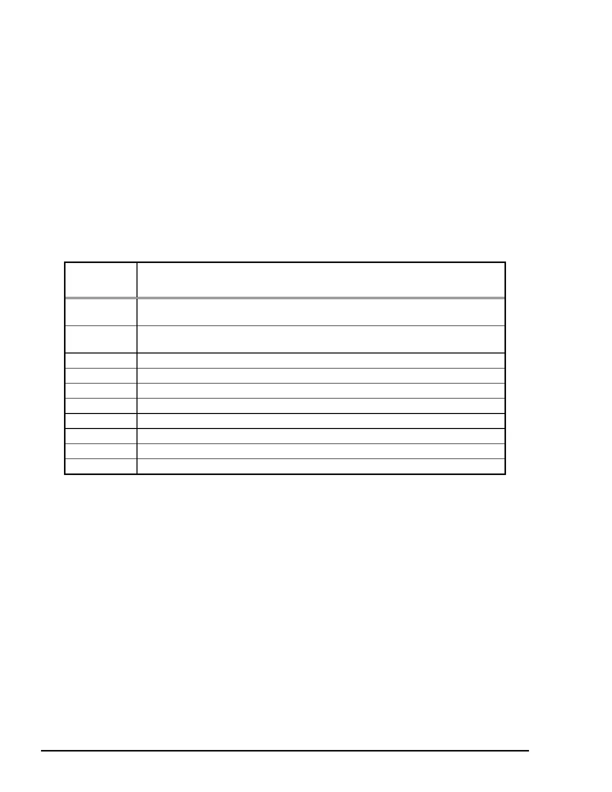
paper width is detected in 10 ranges between 3.86 in (98 mm) and 17.36 in (441 mm). (See Table 2-9.) If the
detected paper width does not match the width for the selected page size, the printer driver shows an error. If
no change is detected in paper size by the ASF PW sensor and ASF PL sensor, the CR PW sensor* is not
activated.
Note: *CR PW sensor: See Page 2-19.
Detecting
Range
Paper Width
(Length between right and left edge guides)
1
3.86 in. ≤ W ≤ 4.28 in. / 4.86 in. ≤ W ≤ 5.59 in.
(98 mm ≤ W ≤ 108.6 mm / 123.4 mm ≤ W ≤ 141.9 mm)
2
5.78 in. ≤ W ≤ 5.98 in. / 7.54 in. ≤ W ≤ 7.39 in.
(146.7 mm ≤ W ≤ 151.9 mm / 161.6 mm ≤ W ≤ 187.8 mm)
3
7.74 in. ≤ W ≤ 10.26 in. (196.6 mm ≤ W ≤ 232.1 mm)
4
9.13 in. ≤ W ≤ 10.26 in. (231.8 mm ≤ W ≤ 260.6 mm)
5
10.87 in. ≤ W ≤ 11.84 in. (276 mm ≤ W ≤ 283 mm)
6
11.56 in. ≤ W ≤ 11.83 in. (293.6 mm ≤ W ≤ 300.6 mm)
7
12.81 in. ≤ W ≤ 13.09 in. (325.4 mm ≤ W ≤ 332.6 mm)
8
13.76 in. ≤ W ≤ 14.47 in. (349.6 mm ≤ W ≤ 367.6 mm)
9
16.4 in. ≤ W ≤ 16.66 in. (416.6 mm ≤ W ≤ 423.1 mm)
10
16.89 in. ≤ W ≤ 17.36 in. (429.1 mm ≤ W ≤ 441 mm)
Table 2-9. Paper Width Range

 Loading...


