EPSON Stylus COLOR 3000
EPSON Stylus Color 3000 Service Manual
-25
Color printhead nozzle selector circuit
The operating principles for the color printhead are the same as for the black printhead, except that color
printing is performed with data for three different colors: cyan, magenta, and yellow. The operating principles
for the color printhead are described below.
Nozzle selector circuit
There are 64 nozzles for each of three colors: cyan, magenta, and yellow. The nozzle selection
signals for each color (CHDATA for cyan, MHDATA for magenta, and YHDATA for yellow) are sent
simultaneously in serial data. The clock signal (CHCLK) is composed of pulses #1 to #64. The latch
signal (CHLAT) synchronizes the nozzle selection signal and the corresponding clock signal to
determine which nozzle should be used. However, the pulse number and the selected nozzle number
are unrelated.
Common driver circuit
The common voltage (VH) and the rank value correspond to each color printhead ID. This value is
stored in advance in the EEPROM when the printer is off. When the printer is on, the value is stored
in the RAM. The gate array E05B33 (IC6) refers to this value and outputs the serial data SCDATA to
the common driver circuit as voltage control signals. The serial data transmission control signals
SCLK, SSTB, and SCLR are used for this operation. The thermistor controls common voltage by
outputting signals to prevent changes in temperature and ink viscosity.
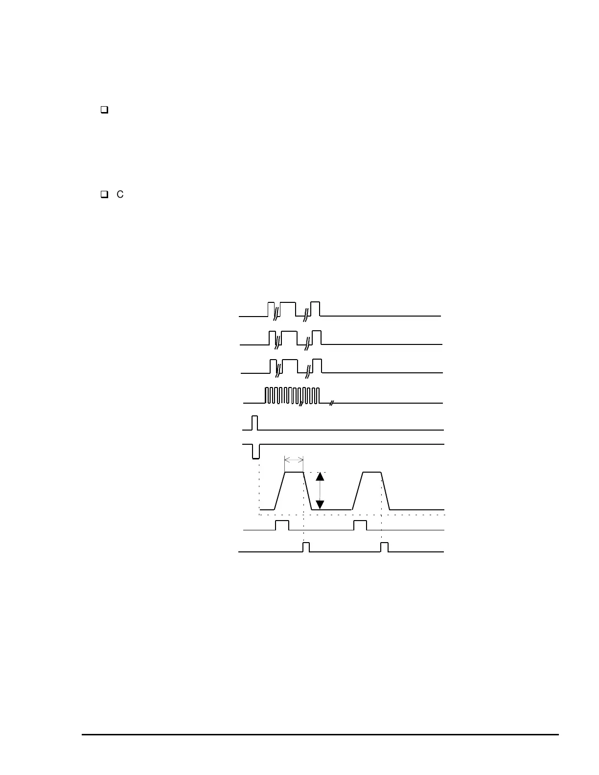
VH
CHLAT
YHDATA
CHCLK
#1
#64
KC,CCHG
CHNCHG
CND0/1
CMD0/1
CHDATA
MHDATA
Printhead Drive Voltage (VH)
Rank Value*
Rank value: The period of time in which the signal COM stays HIGH.
Normal value is approximately 8 ms.
Figure 2-22. Color Data Transmission Timing

 Loading...


