CHAPTER 2
Power Supply
405.1200.037.2 - Rel.: 2.21 of 25/02/2008
2-2
Use a 24VDC (18..32Vdc) power supply unit to power the VT.
Connection
pins
Check all connections before switching on.
Wiring The power supply connector will take conductors with a cross-section of
between 0.05 and 2.5mm² (30-12AWG) for rigid conductors or from 0.05
to 1.5mm² (30-12AWG) in the case of flexible conductors. The length of
the stripped wire must be between 6 and 7.5mm (0.24-0.30in). The recom-
mended screw grip pressure is 0.79Nm (7 lb in).
These values represent the maximum values certificated. The
screw grip pressure is related to the norms applicable to the prod-
uct and to the type of use.
Connections
to be avoided
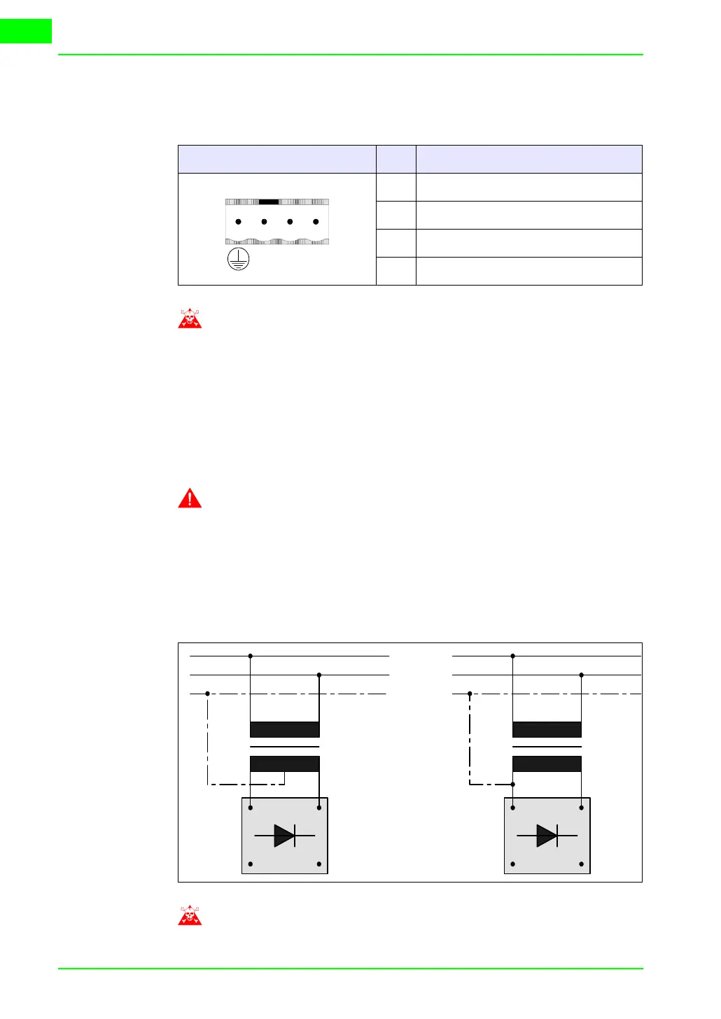
The connections illustrated below must not be made as they may cause the
VT to be damaged.
The above configurations will seriously damage certain compo-
nents of the VT.
Table 2.1: 4 pin Power Supply Connector
Connector Pin Meaning
1 Input power +24Vdc
2 Input power 0Vdc
3 Not connected
4 Earth protection
4321
N.C. 24VDC
-
+
Table 2.2: Connections to be avoided
~
+-
24V
~
+-
24V
PE
N
L1