CHAPTER 41
Connection cables
405.1200.037.2 - Rel.: 2.21 of 25/02/2008
41-14
Characteristics of the arrays:
N.B. :
• Defining the length of the arrays in the programming SW, ELAU puts
the number 1 for the first element of the array; this implies the existence
of an offset of 1 between the address of the array element and the
address specified in the VT variable. E.g.: if, using the VT, you want to
read and edit the element at single word 20 of the array …W4000, num-
ber 19 will have to be specified as the address of the VT variable.
• To have retentive data in the ELAU device, the relevant array must be
declared as VAR_RETAIN.
• Check that the ModBus address assigned in the configuration of the
device in VTWIN corresponds to the value assigned to the parameter
Modbus_SlaveNr of the ELAU Function Block.
EUROTHERM DRIVE
Name Type of data Notes
….B0000
Bit
(read / write)
The VT accesses this data area in both read and write
….B0001
Bit
(read only)
The VT cannot access this data area
….W3000
Word
(read only)
The VT accesses this data area by selecting the option Input
Register as data area of the variabile in the VT .
Warning: The programmer must check that the change
of the data field of the VT page does not get enabled. If
the change of the data field is enabled the equivalent
address in Array ….W4000 will be overwritten.
….W4000
Word
(read / write)
The VT accesses this data area in both read and write by
selecting the option Word as data area.
16
18
470 Ω
1/4 W
15
4
5
RTS
CTS
7
25
GND
TxRx-
22
10
TxRx+
220 Ω
1/4 W
7
470 Ω
1/4 W
4 SHD
TxA
RxB
RxA
5
6
1
2
TxB
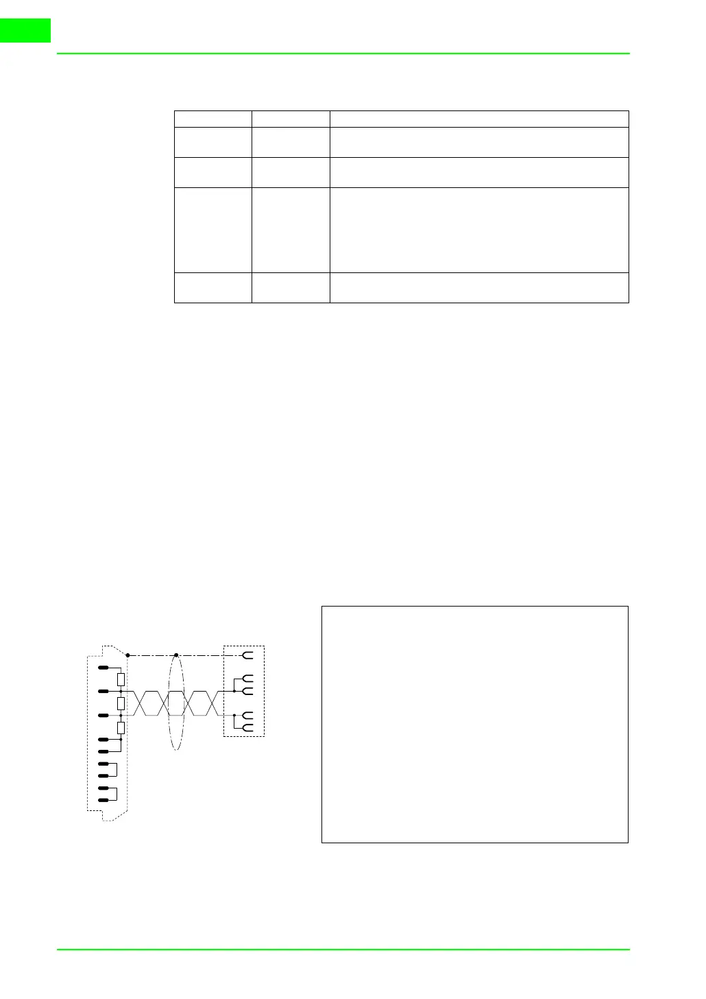
VT side
D-Sub
25 pin male
Order code:
NOT CODED
Series 605
(RS485)
Requires 584SV/605 communication card
WARNING!!! For Hardware configuration refer to manual “RS485 Communication
Interface - HA463560 Issue 1” remembering that Dip-Switch SW1 DIP1 must be
set at OFF and if it is the last in the chain DIP2 is set at ON (Terminated).
For Software configuration refer to the same manual, remembering that the proto-
col DBUS RTU must be selected.
(See “Chapter 41 -> Connecting the cable shield“)
Drive side.
Phoenix
6 pin female