CHAPTER 35
Network connection
405.1200.037.2 - Rel.: 2.21 of 25/02/2008
35-12
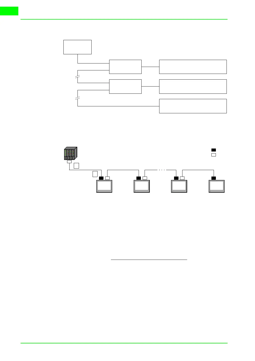
Interbus-S:
Physical
diagram
Below is a physical diagram of the VT <-> Interbus-S connections.
Interbus-S:
Connection
Below is a diagram of the connections between the VTs and the devices in
Interbus-S network.
Parameter n stands for the maximum number of terminals that can be con-
nected in the network, which depends on the size of the memory available
in the master device for the input and output of process data. Each VT con-
nected occupies 64 bits for the data input area and 64 bits for the process
data output; thus
Below we list the connection cables required.
Interbus-S
Master
ESA Module
Interbus-S
VT170W and VT190W with inte-
grated Interbus-S module
All VTs
ESA Module
Interbus-S
All VTs
Slave
Master
VT#1
VT#2 VT#n-1
VT#n
In
Out
A
B
64 bit
I/O area of master device
n =