CHAPTER 3
Video terminal VT50
405.1200.037.2 - Rel.: 2.21 of 25/02/2008
3-12
To fix the sealing gasket and secure the VT to the container see “Chapter 30
-> Mounting the terminal within the container“
.
Where accessories need to be fixed in or onto the VT terminal, you
are advised to do this before securing the VT to its container.
Accessories Any accessories should be mounted in accordance with the instructions in
the relevant chapter (see
“Chapter 34 -> Video terminal accessories“).
Termination of
CAN line
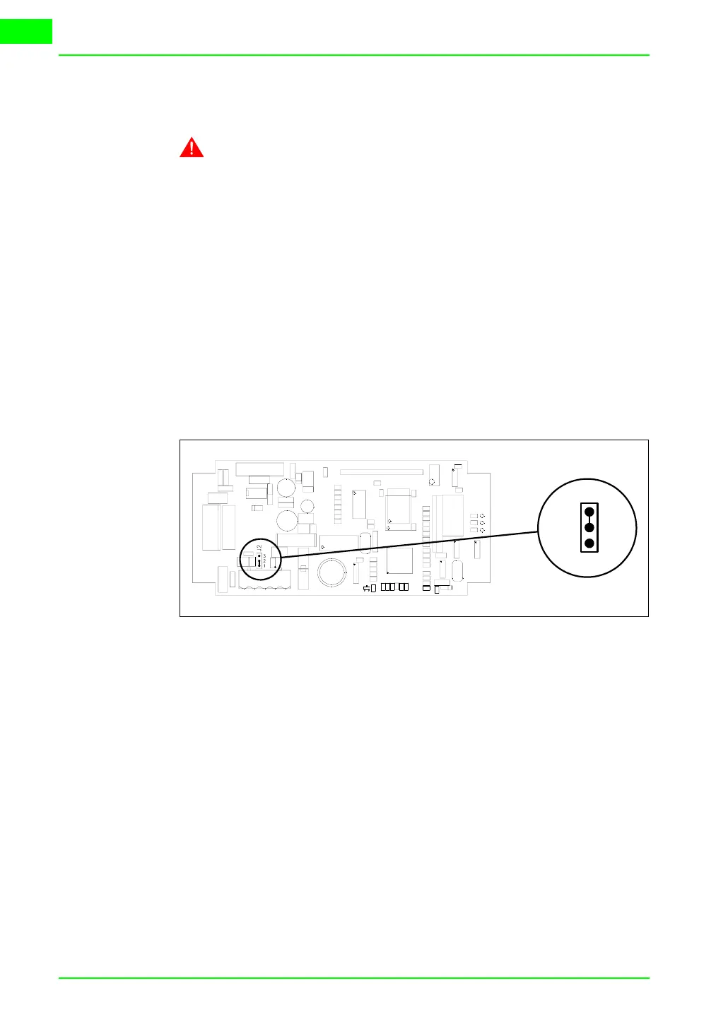
This paragraph applies only to the CAN series. The VT in question inte-
grates the termination resistances of the serial line (typically 120 ohms)
which can be inserted by means of a jumper (preset on 1-2, line not termi-
nated). To activate the termination:
• Make sure the device is not connected to the power supply.
• Remove the cover.
• Identify the jumper unit J2.
• Position the jumper between pins 2 and 3 (line terminated).
• Replace the back cover.
• Reconnect the power supply.
Transfer PC ->
VT
For everything to function properly, the first time the VT operator terminal
is switched on it needs to be correctly loaded, that is it needs to have trans-
ferred to it:
• Firmware
• Communication driver
• Project
(Given that the transfer of the three files in practice occurs with a single
operation, it will be defined as “Project transfer” for the sake of simplicity)
or:
T
J2
3
2
1