CHAPTER 41
Connection cables
405.1200.037.2 - Rel.: 2.21 of 25/02/2008
41-64
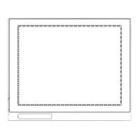
SATT CONTROL PLC
16
18
470 Ω
1/4 W
15
4
5
RTS
CTS
7
25
GND
Rx+
Rx-
7
470 Ω
1/4 W
VCC
Tx-
23
12
Tx+
38
220 Ω
1/4 W
Rx-
13
37
24
Rx+
36
220 Ω
1/4 W
Tx+
Tx-
39
SHD
VT side
D-Sub
25 pin male
Order code:
NOT CODED
PCD2 serial interface 3 module PCD2/F520
(RS422)
B: To make the terminal function with the additional interface of the SAIA PCD
PLC, the following setting must be observed:
SASI 1 (1=first interf., 2=second interf., etc.)
999
;TEXT 999
"UART:9600,7,E,1;MODE:SD0;DIAG:F260,R500;RBUF:255;TBUF:255"
NB: Insert the interface termination resistances (See SAIA manual).
(See “Chapter 41 -> Connecting the cable shield“)
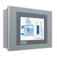
PLC side
Terminals
7
+20mA
+Tx
14
9
+20mA 15
+Rx 18
-Rx
-Tx
25
11
CTS
4
5
GND
RTS
SHD
+R
14
-Rx
17
13 +Tx
16 -Tx
VT side (Active)
D-Sub
25 pin male
Order code:
NOT CODED
PCD2 interface to module TTY - 20mA (PCD7/F130)
(Current loop)
(See “Chapter 41 -> Connecting the cable shield“)
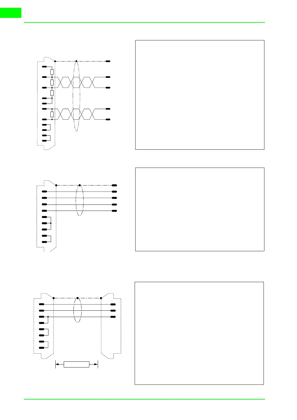
PLC side
terminal
RxD
TxD
RTS
CTS
GND
3
2
7
25
TxD
RxD
GND
3
2
7
4
5
15
18
VT side
D-Sub
25 pin male
PLC side
D-Sub
25 pin male
Max. 15 m.
Order code:
CVPLC18102
Series 31-90
(RS232)
PLC serial port configuration:
Channel Configuration no.: B
COMLI: C
Master / Slave (M / S): S
Identity (1..247): 1
ASCII / Binary (A / B): B
Baudrate (110...19200): 9600
Number of data bits: 8
Number of stop bits: 1
Parity (O / E / N): O
Error counters to register (RX/N): N
Number of ACIA-errors: 12
Number of BCC-errors: 8
Number of other errors: 4
(See “Chapter 41 -> Connecting the cable shield“)
 Loading...