CHAPTER 33
Connection cable for H Series terminals
405.1200.037.2 - Rel.: 2.21 of 25/02/2008
33-8
It is possible to connect with the PC to transfer the project, as follows.
The use of a female 25-pole connector allows to use a standard
CVCOM11102 cable for the transfer (see also
“Chapter 31 -> PC
<-> VT connection“
).
Lay-out of
button
functions
System shut-down button
Enabling button
The system shut-down button and the enabling button do NOT
guarantee the operatr’s complete personal safety. Be sure to
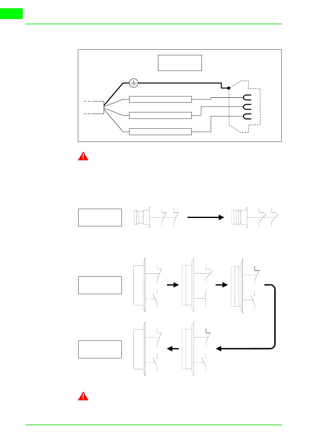
TX RS232 OUT - MSP
RX RS232 IN - MSP
Signal GND
TxD
RxD
GND
2
3
7
VT Side
25 pin female
NC3
NC4
NC1
NC2
NC1
NC2
NC3
NC4
Pushing
button
NC1
C1
NO2
C2
NO2
C2
NC1
C1
NO2
C2
NC1
C1
NC1
C1
NO2
C2
NO2
C2
NC1
C1
NC1
C1
NO2
C2
NC1
C1
NO2
C2
Pushing
button
Releasing
button