CHAPTER 71
PAGE 3
SERVICE MANUAL EXTRA 300LT
PAGE DATE: 21. March 2014
71-10-00 COWLING
Description
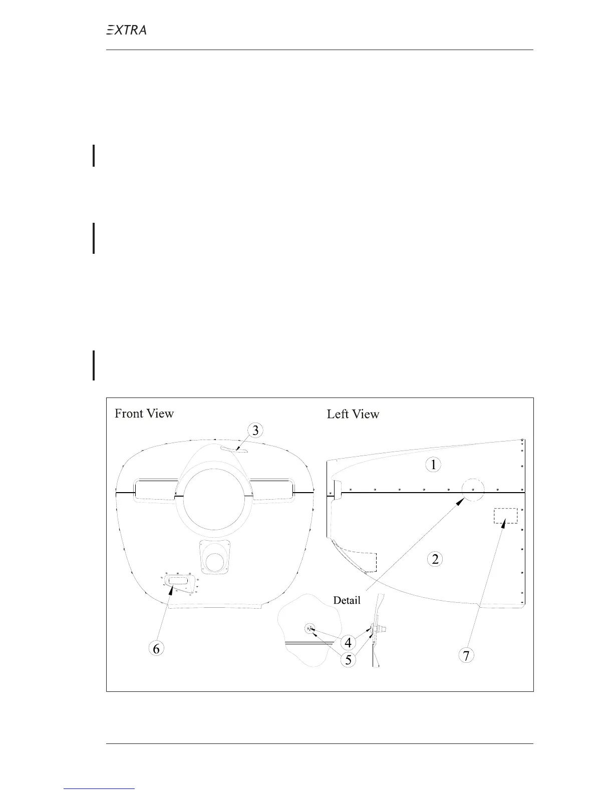
The engine cowling is divided into two parts: The top half (1,
figure 1) and bottom half (2) made of CFRP honeycomb
sandwich.
The top half of the engine cowling features a hinged hatch (3)
for access to the oil dip stick. This hatch is opened by two
slotted head flush type Camloc
®
retainers. The bottom half
features a Xenon or LED landing light (6). The Xenon power
supply (7) and the electrical connector are installed on the
left aft inside.
Both cowling halves are attached to each other and the
airframe by means of truss head screws (4) and special
washers (5).
The interior surface of both cowling halves is coated with a
fire protection paint which is sealed by varnish coating (up to
SN LT024). Additional aluminized heat blankets are placed
in the bottom cowling half.
Figure 1 Engine Cowling