Summit X250e Series Switches
Extreme Networks Consolidated ExtremeXOS Hardware Installation Guide
243
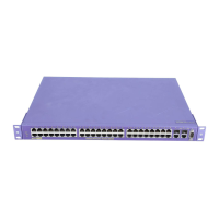
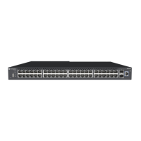
Figure 167: Summit X250e-24t switch front panel
The front panel on the Summit X250e-24t switch includes:
● LEDs—For a description of the LEDs and their operation, see “Summit X250e Series Switch LEDs”
on page 250.
● Stack number indicator—Numeric indicator of the position of this switch in a stacked configuration.
● 10/100BASE-T Ethernet ports—Twenty-four 10/100BASE-T Ethernet ports that deliver high-density
copper connectivity.
● Combination ports—Two combination ports that provide 10/100/1000 BASE-T or mini-GBIC
connectivity for 2 Gbps of copper or fiber connectivity.
● Console port—Serial port used to connect a terminal and perform local management.
Summit X250e-24t Switch Rear Panel
Figure 168 shows the rear panel of the Summit X250e-24t switch.
Figure 168: Summit X250e-24t switch rear panel
The rear panel on the Summit X250e-24t switch includes:
● Management port
■ Used to connect the system to a parallel management network for administration.
OR
■ Used to connect an Ethernet cable directly from a laptop into the management port to view and
locally manage the switch configurations.
● Two LEDs for the management port, located in the bottom corners of the port.
1
2
Stack
SH_038A
10/100 Mbps ports
Console
port
Shared ports Stack number indicator
SH_039
Redundant Power Input
! See Manual
10 Gigabit
stacking ports
Management port
Power socket
External power
supply connection

 Loading...