Summit X450e Series Switches
Extreme Networks Consolidated ExtremeXOS Hardware Installation Guide
271
Summit X450e-24p Switch Front Panel
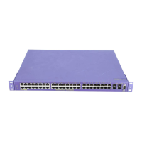
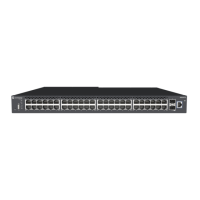
Figure 191 shows the front panel of the Summit X450e-24p switch.
Figure 191: Summit X450e-24p switch front panel
The front panel on the Summit X450e-24p switch includes:
● LEDs—For a description of the LEDs and their behavior, see “Summit X450, X450a, and X450e Series
Switch LEDs” on page 276.
● Stack number indicator—Numeric indicator of the position of this switch in a stacked configuration.
● Combination ports—Four combination ports that provide 10/100/1000 BASE-T PoE or mini-GBIC
connectivity for 4 Gbps of copper or fiber connectivity.
● 10/100/1000 BASE-T PoE ports—Twenty 10/100/1000 BASE-T PoE ports that deliver high-density
copper connectivity and a full 15.4 Watts of PoE per port
● Console port—Serial port used to connect a terminal and perform local management.
Summit X450e-24p Switch Rear Panel
Figure 192 shows the rear panel of the Summit X450e-24p switch.
Figure 192: Summit X450e-24p switch rear panel
STACK NO.
PORTS 1 -24
POWERED (AMBER) ON=LINK
NO POWER (GREEN) ON=LINK
FLASHING=ACTIVITY
OFF=NO LINK/DISABLED
ALTERNATE AMBER/GREEN=PWR FAULT
FLASHING=ACTIVITY
OFF=NO LINK/DISABLED
MGMT
FAN
PSU-1
PSU-E
1
10G
Stack
2
1
2
214365871091211 1413 1615 1817 2019 2221 2423 22X21X 24X23X
Shared Ports
SH_015A
10/100/1000 Mbps PoE ports
Console
port
Shared ports
Stack number
indicator
SH_027
10 Gigabit
uplink option
Management port
10 Gigabit
stacking ports
Power socket
External power
supply connection

 Loading...