Configuring Spanning Tree Protocol (STP) and IronSpan Features
December 2005 © Foundry Networks, Inc. 7 - 41
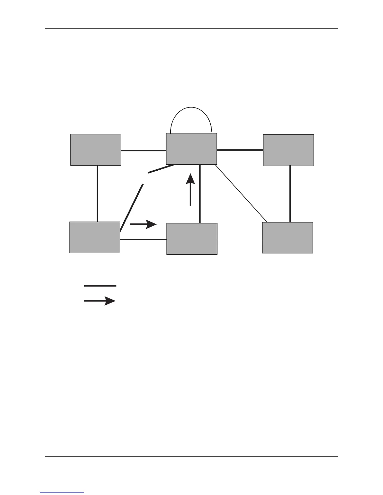
For example, Port3/Switch 2 in Figure 7.20, fails. Port4/Switch 3 becomes the new Root port. Port4/Switch 3
sends an RST BPDU with a TCN to Port4/Switch 4. To propagate the topology change, Port4/Switch 4 then starts
a TCN timer on itself, on the bridge’s Root port, and on other ports on that bridge with a Designated role. Then
Port3/Switch 4 sends RST BPDU with the TCN to Port4/Switch 2. (Note the new active Layer 2 path in Figure
7.20.)
Figure 7.20 Beginning of Topology Change Notice
Port2 Port2
Port7 Port8
Port3
Port3
Port4Port4
Port3
Port2
Port3
Bridge priority = 200
Switch 4
Bridge priority = 400
Bridge priority = 300
Bridge priority = 1000
Port4
Port5
Port3
Port3
Switch 6
Bridge priority = 900
Bridge priority = 60
Port2
Port5 Port5
Port4
Indicates the active Layer 2 path
Indicates direction of TCN
Switch 1
Switch 2
Switch 5
Switch 6
Switch 4
Switch 3