Foundry Configuration Guide for the FESX, FSX, and FWSX
11 - 16 © Foundry Networks, Inc. December 2005
EXAMPLE: 1
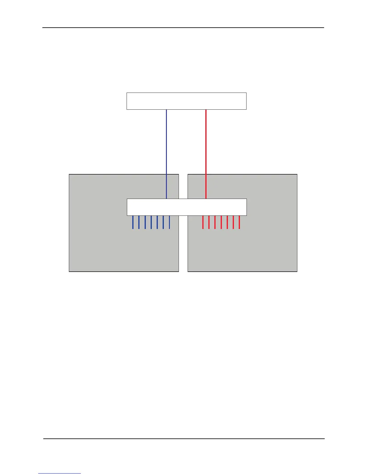
Figure 11.9 shows a simple port-based VLAN configuration using a single Foundry Layer 2 Switch. All ports
within each VLAN are untagged. One untagged port within each VLAN is used to connect the Layer 2 Switch to a
Layer 3 Switch (in this example, a FSX) for Layer 3 connectivity between the two port-based VLANs.
Figure 11.9 Port-based VLANs 222 and 333
To create the two port-based VLANs shown in Figure 11.9, enter the following commands:
FESX424 Switch(config)# vlan 222 by port
FESX424 Switch(config-vlan-222)# untag e 1 to 8
FESX424 Switch(config-vlan-222)# vlan 333 by port
FESX424 Switch(config-vlan-333)# untag e 9 to 16
Syntax: vlan <vlan-id> by port
Syntax: untagged ethernet [<slotnum>/]<portnum> [to [<slotnum>/]<portnum> | ethernet [<slotnum>/]<portnum>]
EXAMPLE: 2
Figure 11.10 shows a more complex port-based VLAN configuration using multiple Layer 2 Switches and IEEE
802.1Q VLAN tagging. The backbone link connecting the three Layer 2 Switches is tagged. One untagged port
within each port-based VLAN on FESX-A connects each separate network wide Layer 2 broadcast domain to the
router for Layer 3 forwarding between broadcast domains. The STP priority is configured to force FESX-A to be
the root bridge for VLANs RED and BLUE. The STP priority on FESX-B is configured so that FESX-B is the root
bridge for VLANs GREEN and BROWN.
VLAN 222
Ports 1 - 8
VLAN 333
Ports 9 - 16
FSX Router
Ports 2 - 8
IP Subnet 1
IPX Network 1
AppletalkCable-Range 100
AppletalkZonePrepress
Ports 9 - 16
IP Subnet 2
IPX Network 2
AppletalkCable-Range 200
AppletalkZone CTP
interface e 2
IP Subnet 2
IPX Network 2
AppletalkCable-Range 200
AppletalkZone CTP
interface e 1
IPX Network 1
AppletalkCable-Range 100
AppletalkZonePrepress
IP Subnet 1
Port 9Port 1
FESX