Foundry Switch and Router Installation and Configuration Guide
9 - 18 December 2000
Chassis
Chassis support two different modules with two different LED indicator types, Ethernet/Fast Ethernet and Gigabit
Ethernet. Ethernet modules have two port LED indicators, as defined in Table 9.3. LEDs for Gigabit Ethernet ports
are defined in Table 9.4.
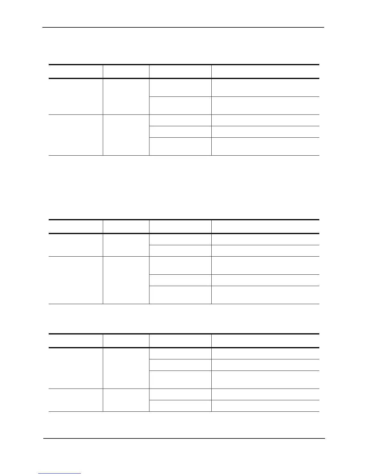
Table 9.2: Port LED indicators for earlier Stackable 10BaseT/100BaseTX systems
LED Position State Meaning
FDX Top On Full-duplex connection found or
configured.
Off Half-duplex connection or no port
connection exists.
Link/Activity Bottom On Connection established, no activity.
Off No connection established.
Blinking Connection established with activity on
the link.
Table 9.3: Port LED indicators for 100BaseFX, 1000BaseSX/LX, and 1000BaseT ports
LED Position State Meaning
Link Top On Port is connected.
Off No port connection exists.
Activity Bottom On Traffic is being transmitted and received
on that port.
Off No traffic is being transmitted.
Blinking Traffic is being transmitted and received
on that port.
Table 9.4: Port LED indicators for 10BaseT/100BaseTX chassis modules
LED Position State Meaning
Link/Activity Left On Port is connected.
Off No port connection exists.
Blinking Traffic is being transmitted and received
on that port.
FDX Right On The port is operating at full-duplex.
Off The port is operating at half-duplex.